
Proven Protection Technique
The best protection technique now and for more than 50 years is that known as differential protection. Here the electrical quantities entering and leaving the protected zone or area are compared by current transformers (CTs). If the net between all the various circuits is zero, it is assumed that no fault or intolerable problem exists.
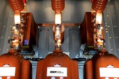
 Differential Protection – Proven Technique For More Than 50 Years (on photo: Medium voltage switchgear type MCSET and SEPAM protection relays by Schneider Electric)
However, if the net is not zero, an internal problem exists and the difference current can operate the associated relays. In general, internal faults provide significant operating current, even for fairly light faults.
Differential practice
This fundamental technique is illustrated in Figure 1 below, and for simplicity, only two circuits in the protection zone are shown. Multiple circuits may exist, but the principle is the same.
The sum of the currents flowing in essentially equals the sum of the currents flowing out during normal operation.

- (a) normal conditions, IOP = Ie″ + Ie′;
- (b) internal fault IOP = IF1 + IF2 – (Ie′ + Ie″)
The voltage differential system is similar and not discussed here.
For normal operation and all external faults (the though condition), the secondary current in Figure 1a in the protective relay is the difference in the exciting currents of the differentially connected current transformers. Per-unit current distribution is also shown in the figure.
For example, Ip is the primary current in the lines entering or leaving the protected area. Ip – Ie is the secondary ampere current and is equal to the primary current divided by the current transformer ratio minus the secondary exciting current. Even with exactly the same ratio and type of current transformer, the relay current IOP will be small, but never zero. This is because of the losses within the protected area and small differences between the same CTs.
During external faults the transient performance of the several CTs resulting from the sudden increase in current and the associated offset (DC component) can produce rather large transient-operating currents. Thus, it is difficult and impractical to apply an instantaneous relay. Time-delay relays can be used, but with care.
For internal faults, Figure 1b shows that the differential relay operating current is essentially the sum of the input currents feeding the fault. This is the total fault current on a secondary ampere basis.
Except for very light internal faults, good discrimination is available to detect problems (faults) within the differential zone. For the differential relay to operate, it is not necessary for all the circuits to supply fault current if no current is supplied to the fault.
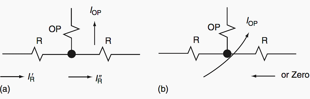
To provide high sensitivity to light internal faults with high security (high restraint) for external faults, most differential relays are of the percentage differential type. Figure 2 is a simplified schematic of this type of relay for two circuits, as shown in Figure 1.
The secondary of the CTs are connected to restraint windings R and currents in these inhibit operation. Associated with these restraint windings is the operating winding OP. Current in this winding tends to operate the relay. Differential relays may be either fixed or variable that tends to operate the relay.
These may be of either fixed or variable percentage, and typical characteristics are illustrated in Figure 3 below.
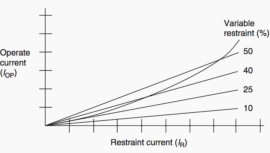
The abscissa is the restraint current. This can be either the smaller current (IR″) or the larger current (IR′) depending on the design. The ordinate is the current (IOP) required to operate the relay. Fixed percentage relays exist between 10% and 50% and may or may not have taps to change the percentage.
Thus with a 50% characteristic, an external or through current of 10A would require a difference or operating current of 5A or more for the relay to operate. With a 10% type, and 10A through current, I A or more difference current would produce relay operation.
The variable percentage types do not have percentage taps. At low through currents the percentage is low because at these levels the current transformer performance is usually quite reliable. At high through-fault currents, where the CT performance may not be as dependable, a high percentage characteristic is provided. This gives increased sensitivity with higher security.
It is important to recognize that characteristics, such as those shown in Figure 3, apply only to external faults or through current flow.
Differential relays are quite sensitive to internal faults when the currents in the restraint windings are in opposite directions or one of the restraint current is zero, as in Figure 2. These relays are calibrated with current through one restraint and the operating windings with no current through the other restraint(s). Typical pickup currents for differential relays are of the order of 0.14A – 3.0A, depending on the type, tap, and application.
For equipment, such as generators, buses, transformers, motors, and so on, the CTs usually are all in the same general area, so that it is not too difficult to interconnect their secondaries with the relays.
For lines where the terminals and CTs are separated by considerable distances, it is not practically possible to use differential relays as described earlier. Yet, the differential principle provides the best protection and is still widely used. This is true particularly at the higher voltages.
A communication channel, such as a pilot wire (wire or fiber-optic cable), power line carrier (radio frequency), audio tones over wire, or microwave is used for information comparison between the various terminals.
Transformer Differential Protection (VIDEO)
Line Differential Protection Fundamentals
Reference // Protective Relaying Principles and Applications by J. Lewis Blackburn and Thomas J. Domin (Purchase from Amazon![]() )
)


muy buenos documento muy bien redactados y la información ideal
I need more explanation on electrical protection
Very nice and good article