Phase faults and large fault currents
Generally, phase faults at generators rarely occur, but when they do, large fault currents can flow and make a mess. The best protection is differential (ANSI 87), and this type is recommended for all generators, except maybe for small units of 1 MVA and less. It’s important to note that this provides sensitive protection to phase faults, but may not provide ground fault protection, depending on the type of grounding used.

Let’s describe now the six most important differential stator phase-fault protection (87) for all size generators:
- Differential protection (87) for small kVA (MVA) generators
- Multi-CT differential protection (87) for all size generators
- High-impedance voltage differential protection for generators
- Direct-connected generator current differential example
- Phase protection for small generators that do not use differentials
- Unit generator current differential (87) example for phase protection
1. Differential protection (87) for small kVA (MVA) generators
The preferred method for small units is shown in Figure 1. The limitation is the ability to pass the two conductors through the window or opening of the CT. Typical opening diameters are about 4–8 in. However, where this is possible, high-sensitivity, high-speed protection is obtained, and CT performance does not have to be matched, for there is only one involved per phase.
The flux summation CT ratio (commonly 50:5) is independent of generator load current. Typical sensitivities in the order of 5 A primary current can be obtained. This provides protection for both phase- and ground-fault currents as long as the fault level for faults within the differential zone is greater than the sensitivity.
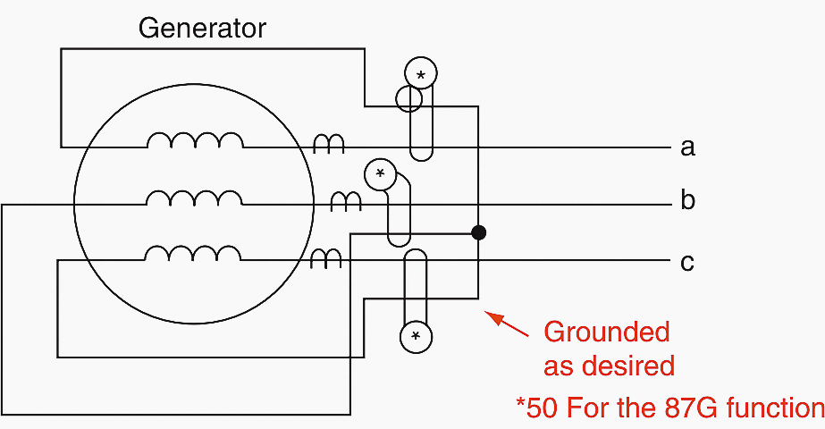

This scheme does not provide protection to the connections from the flux summation CT to the generator breaker, unless the CT is on the bus side of the breaker and the generator neutral side leads are carried to that point. This is seldom practical, so other protection must be provided for this area between the flux summation CT and the breaker.
In general, this scheme (see Figure 1) is more sensitive as long as the generator CT ratio is greater than 150:5 to 200:5. If the flux summation CT is not applicable and differential protection is desired, the schemes of Figure 2c and Figure 2d can be used. See below.
2. Multi-CT differential protection (87) for all size generators
This protection is widely used to provide fast and very sensitive protection to the generator and associated circuits. The 87 relays are connected to two sets of current transformers; one set in the neutral leads, the other in the line side.
For generators with associated breakers, the line-side CTs are usually associated with the breaker, as shown in Figure 2a and Figure 2b.
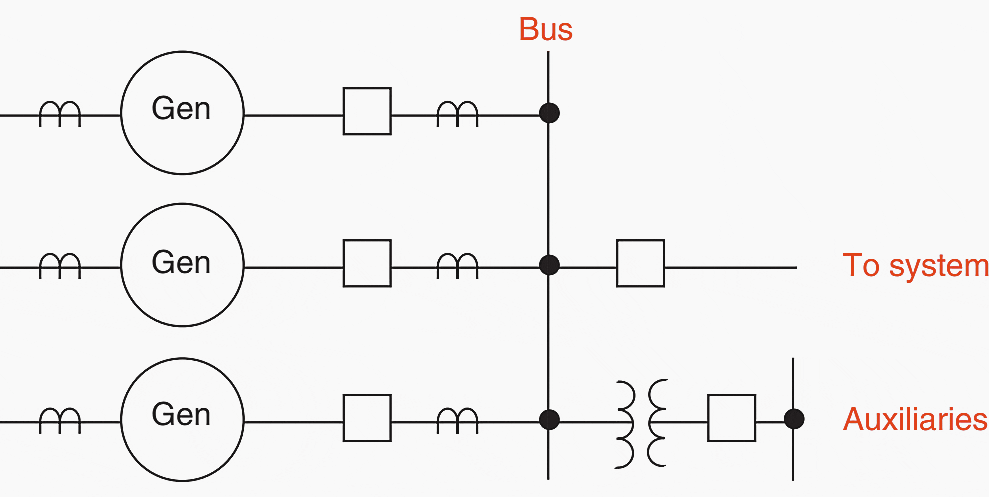

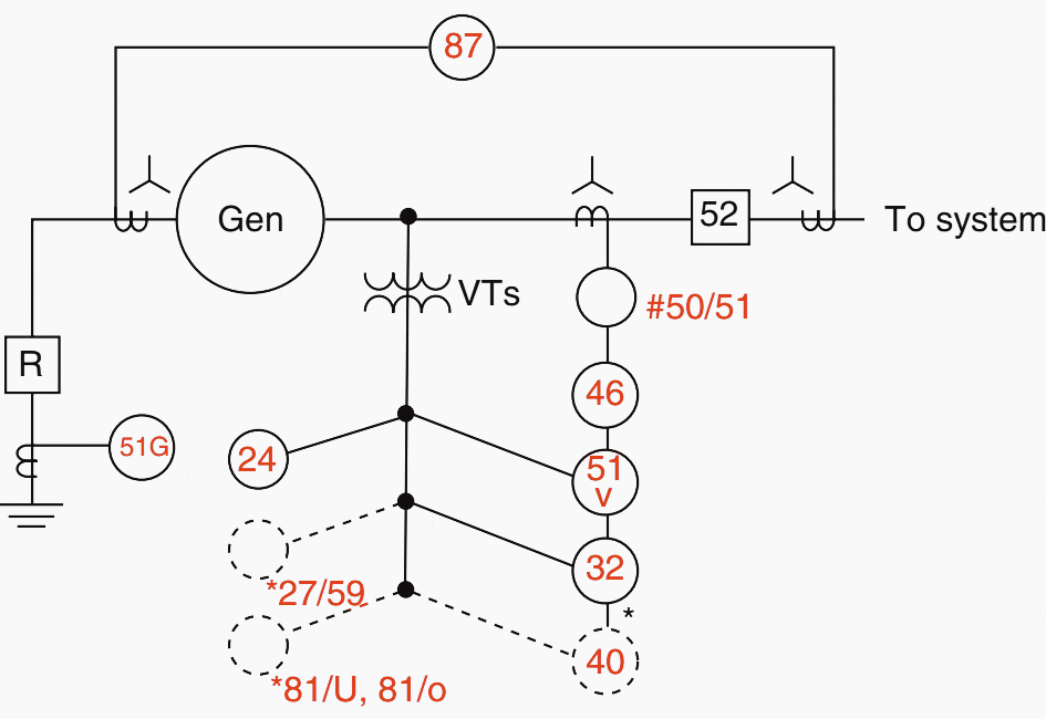

For unit generators the line-side CTs are usually quite close to the generator, basically at the generator terminals. Typical connections for the three-phase units are shown in Figure 2c and 2d for both wye- and delta-connected generators.

If current transformers are available at each end of the windings for the delta-connected generators of Figure 2d, the differential relays can be applied for winding protection. The connections would be similar to those shown in Figure 2c.
However, this would not provide protection for the junction points or the phase circuits that are within the protection zone (see Figure 2d).


Usually, the differential CTs have the same ratio, and they should preferably be of the same type and manufacture to minimize mismatch errors for external faults. This is difficult for generators of Figure 2a and Figure 2b, where the CTs in the neutral are one type and those associated with the breaker are another type.
It is preferable not to connect any other equipment in the differential circuit and to keep the lead burden as low as possible.
Generally, the impedance of the restraint winding of differential relays is low. All this contributes to a totally low-burden and increased performance margins for the CTs.
Unfortunately, the flux in the machine continues to supply the fault for several seconds (about 8–16 sec), so instantaneous de-energization of generator faults is not possible. Problems with magnetizing inrush generally are not severe because the voltage on the machine is developed gradually, and the generator is carefully synchronized to the power system.
However, the differential relays should have good immunity to avoid incorrect operation on an external fault that significantly lowers the voltage, which recovers when the fault is cleared. This can cause a ‘‘recovery inrush’’. This is not applicable to those units that are subject to energizing a transformer or power system at full voltage (black start).
Cross-compound generators have two units, generally connected to a common power transformer. For these units a separate differential relay is applied for each generator unit connected (see Figure 2c above).
Split-winding generators, where the two winding halves are available with CTs in one of the halves (Figure 3), can be protected with two separate differentials.


By comparing one winding half against the total, as shown, protection for shorted turns and open-circuited windings is possible. This is difficult or impossible for conventional relaying until the fault develops into the other phases or the ground. Where a 2:1 CT ratio is not available, auxiliary CTs can be used.
3. High-impedance voltage differential protection for generators
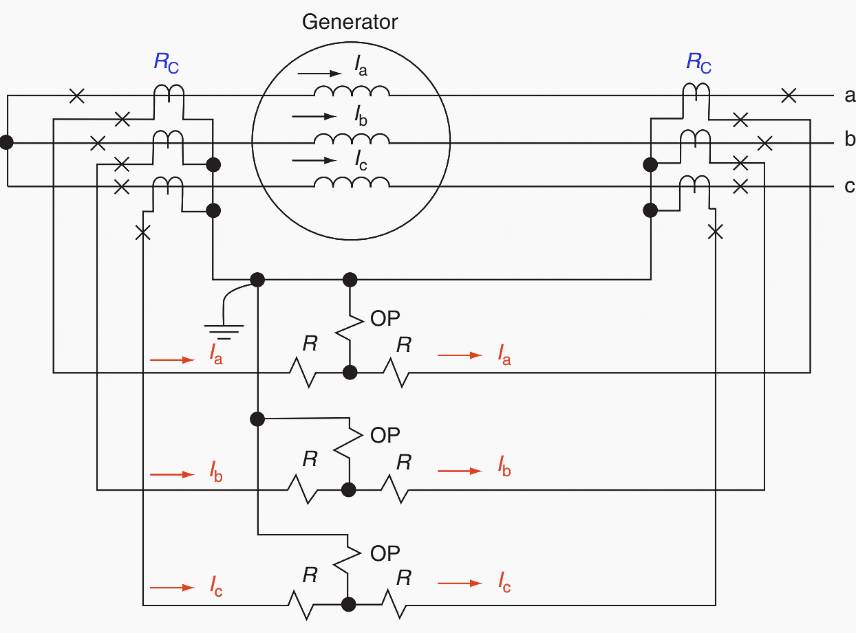
The high-impedance voltage type of differential protection scheme can be applied as an alternative to the current differential type described. The relays are connected between phase and neutral leads of the paralleled CTs.
- For external faults, the voltage across the relay will be low, because the current circulates between the two sets of CTs (see Figure 1).
- For internal faults, the fault currents must pass through the exciting branch and high-impedance relay of each CT, so that the CTs are saturated for most faults, producing a high voltage to operate the relay.
This protection scheme is widely used for bus protection and is described further below. The CT requirements are more or less critical. They should have identical characteristics, negligible leakage reactance, and fully distributed secondary windings.
More about bus protection:
4. Direct-connected generator current differential example
A 20 MVA generator is connected to a 115 kV power system, as shown in Figure 4. The 87 differential relays are connected to the generator neutral
and circuit breaker CTs. On a 20 MVA base, the equivalent system reactance is 20/100(0.2) = 0.04 pu.
For this, in an internal three-phase fault at F, the total reactance to the fault is:
- X1 = (0.32 × 0.14) / 0.46 = 0.097 pu
- I30 = 1/0.097 = 10.27 pu at 20 MVA
- I30 = 10.27 × 20,000/(√3 × 13.8) = 8593.5 A at 13.8 kV
- Imax load = 20,000/(√3 × 13.8) = 836.74 A at 13.8 kV
Selecting 1000:5 CTs (Rc = 200) Imax load = 4.18 A secondary. With this CT ratio, I30 = 42.96 A, in the 87 relay-operating coil. This is many multiples of the typical pickup of about 0.4 A for positive and fast operation.


If the three-phase fault occurred before the generator was synchronized to the power system,
- I30 = 1/0.32 = 3.13 pu = 2614.8 A at 13.8 kV
- I30 = 13.1 A through the 87 operating coil
For an internal ground fault at F, I0g = 400/200 = 2.0 through the operating coil
With the 87 phase relays set to operate at 0.4 A, the solid ground fault of 2.0 A is five times the relay pickup. Thus, ground fault protection is provided, but should be supplemented with 50N/51N overcurrent relays connected in the grounded neutral.
5. Phase protection for small generators that do not use differentials
Where small power sources are connected to a large system, protection for phase faults or reflection in the ac circuits of these small sources can be obtained from instantaneous overcurrent (50) or time–overcurrent (51) relays. These are connected in the interconnecting phases to operate on fault currents supplied by the large system.
Because these relays are non-directional, they must be coordinated with upstream devices for which the small generators can supply fault current.
This contribution may not exist for some power sources:
They usually exist only for a short time for induction generators (see next paragraph) or are relatively small for synchronous generators. In addition, the current supplied by synchronous generators will decrease with time, from subtransient, to transient, to synchronous, as illustrated in Figure 5a. Induction generators need external sources for excitation.
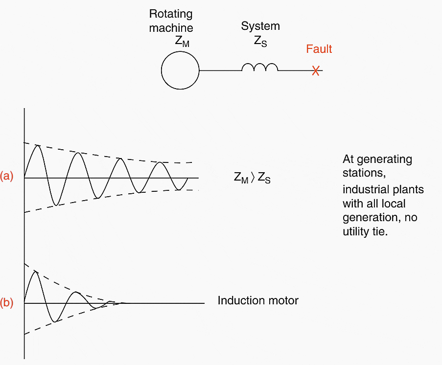

When a fault occurs and reduces the voltage, they generally provide a very short-time contribution to faults, as do induction motors (see Figure 5b). If they are islanded with other induction and synchronous machines, it is possible that the system can supply necessary excitation for the induction generator to continue to supply a fault.
Ground relays may also be used if the large system can supply ground fault current. This is dealt with further under the section on ground protection.
This protection is not possible to operate if the small generator is ungrounded and if it is not connected to the large system.
6. Unit generator current differential (87) example for phase protection
Consider the unit-connected generator tied to a 345 kV power system as shown in Figure 6 below. For a three-phase fault on the 18 kV bus at F1, the positive-sequence network is shown and the total reactance to the fault is calculated as:


These values are per unit on a 100 MVA base. The values in parentheses define current distribution on either side of the fault.
For a solid three-phase fault:
- I1F1 = IaF1 = 1/0.064 = 15.70 pu,
- I1 pu = 100.000/(√3×18) = 3,207.5 at 18 kV,
- I1F1 = IaF1 = 15.7 × 3,207.5 = 50,357.3 A at 18 kV
The maximum load on the unit is:
Imax load = 160,000/(√3×10) = 5,132 at 18 kV
The three-phase secondary fault current is:
I1F = IaF1 = 50,357/1,100 = 45.78 A sec.
If the fault F1 is inside the 87 differential zone (see Figure 6) this 45.78 A would flow through the operating coil. This is many multiples of the differential relay pickup current for positive and fast operation.
For the external fault F1 as shown, the currents through the restraining windings of the differential relay would only be the contribution from the generator, which is:
I1F1gen = (50,357.3 × 0.485)/1,100 = 22.2 A sec.
This would be the internal and total fault current if a three-phase fault occurred before the units were synchronized to the 345 kV system. For these cases the fault current can be calculated alternatively as:
- I1F1gen = 1.0/0.131 = 7.62 pu
- I1F1gen = 7.62 × 3207.5 = 24,438.11 A at 18 kV,
- I1F1gen = 24,438.1 / 1,100 =22.2 A sec.
Further reading:
Practical tips for the protection of generators and power transformers
Source: Protective Relaying Principles and Applications by J. Lewis Blackburn and Thomas J. Domin


