
Estimated Study Time: 7 minutes
Testing the charging system
To be honest with you, this article is about testing the car charging system and it isn’t applicable on new Tesla Model III or new BMW 7-series. As you can already guess from the title itself, all testings described below are for older cars with older motors and engines. But, if you consider reading this article from electrical engineering testing aspect, then you’ll be just fine and you can learn something :)
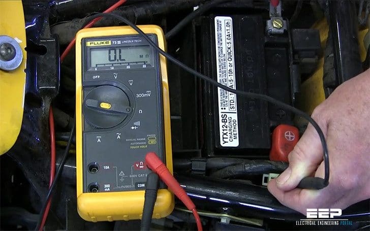 Using digital multimeter for testing of automotive charging system (photo credit: Rick's Motorsport Electrics via Youtube)
Perhaps the most important tool you’ll use in troubleshooting auto electrical systems is the multimeter, usually digital.
Basic multimeters measures: voltage, current and resistance, while more elaborate multimeters, such as for example the Fluke have features that can check things such as frequency, duty cycle, dwell, make diode tests, and even measure temperature, pressure and vacuum.

Important Note!
This technical article is intended as a guide for the professional mechanic. It describes some of the test procedures commonly used by experienced technicians. However, some of the procedures require you to take certain precautions to avoid personal injury and/or damage to equipment or vehicles. Be careful.
Charging System
Batteries
Charging system problems often come to you as a “no-start” complaint. Many people won’t bring a car into the shop until it won’t start, so for a great many failures that’s the first symptom you’ll see. The battery will have discharged and the starter won’t crank the engine.
The first step is to test the battery and charge it if necessary (Figure 1).
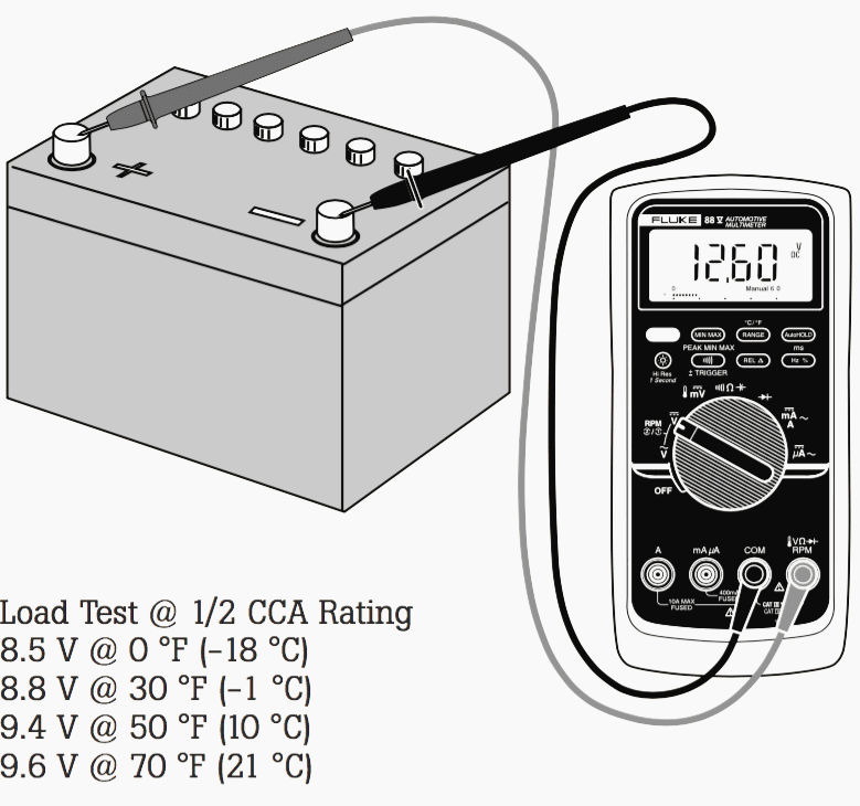
Bleed the surface charge from the battery by turning on the head-lights for a minute. Measure the voltage across the battery terminals with the lights off (see chart ‘Load test at 1/2 CCA rating’). When possible, individual cell specific gravity should be checked with a hydrometer.
A load test should be done to indicate battery performance under load. Voltage tests only tell the state of charge, not the battery condition.
| Voltage | Percent charge |
| 12.60 V to 12.72 V | 100% |
| 12.45 V | 75% |
| 12.30 V | 50% |
| 12.15 V | 25% |
Readings obtained at 80 °F (27 °C)
Alternators
A digital multimeter’s accuracy and digital display make regulator/alternator diagnosis and adjustment easy.
Regulators
First determine if the system has an integral (internal) regulator, then whether it’s type A or B.
- Type-A has one brush connected to batt+ and the other brush grounded through the regulator
- Type-B has one brush directly grounded and the other connected to the regulator
Next, isolate the problem to alternator or regulator by bypassing the regulator (full-fielding). Ground Type-A field terminal. Connect Type-B field terminal to Battery +. If the system now charges, the regulator is faulty. Use a rheostat if possible. Otherwise, just idle the engine (lights on) so the voltage doesn’t exceed 15 V.
The battery must be fully charged (see Figure 1). Run the engine and verify that no-load voltage is 13.8-15.3 V (check as in Figure 1). Next, load the alternator to rated output current with a carbon pile across the battery.
Alternator AC leakage
An alternator generates current and voltage by the principles of electromagnetic induction.
Accessories connected to the vehicles charging system require a steady supply of direct current at a relatively steady voltage level. You can’t charge a battery with alternating current, so it must be rectified to direct current.
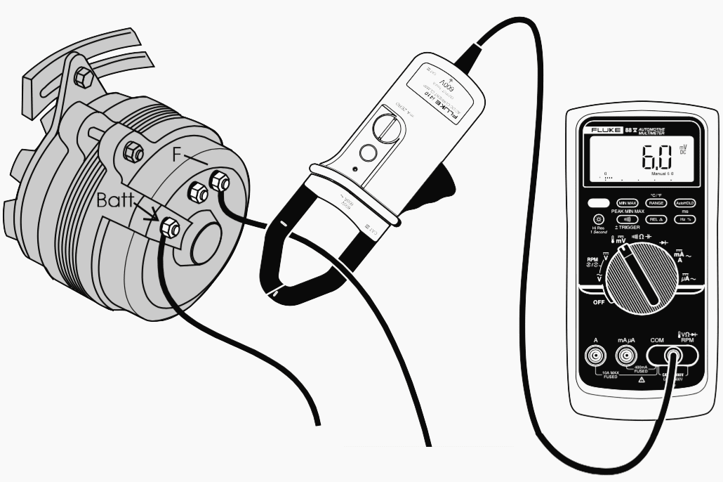
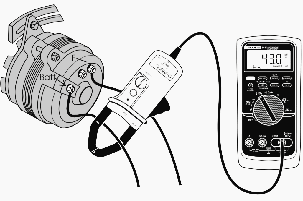
Worn brushes limit field current, causing low alternator output. To test: load unit as in Figure 2 and measure field current with current clamp or use 10 A jack on digital multimeter. Readings range from 3 to 7 amps.
On integral GM units: with alternator not turning, jump terminals together and connect both to Batt + with digital multimeter in series set to measure 10 amps. Field current should be between 2 and 5 amps, higher current with lower battery voltage. Control battery voltage by loading it with a carbon pile.
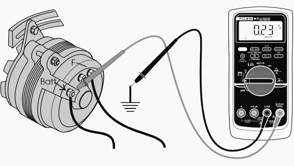
Ripple voltage or (AC voltage) can be measured by switching your digital multimeter to AC and connecting the black lead to a good ground and the red lead to the “BAT” terminal on the back of the alternator, (not at the battery).
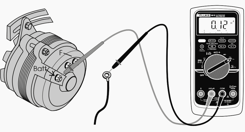
To check alternator diode leakage, connect the multimeter in series with the alternator output terminal when the car is not running.
Leakage current should be a couple of milliamps at most. More often, it will be on the order of 0.5 milliamps. Use care when disconnecting the alternator output wire. Make sure the battery is disconnected first. Connect the meter, then reconnect battery.
Digital multimeter Fluke 88 Demo
Fluke Automotive 2010 DMM Tutorial F233 and others
Reference // Beat the Book – Automotive electrical diagnosis. Better diagnosis, faster repair by Fluke
Related electrical guides & articles


Edvard Csanyi
Hi, I'm an electrical engineer, programmer and founder of EEP - Electrical Engineering Portal. I worked twelve years at Schneider Electric in the position of technical support for low- and medium-voltage projects and the design of busbar trunking systems.I'm highly specialized in the design of LV/MV switchgear and low-voltage, high-power busbar trunking (<6300A) in substations, commercial buildings and industry facilities. I'm also a professional in AutoCAD programming.
Profile: Edvard Csanyi

Thanks for the article, really helpful.
You’re welcome Mayank, I’m glad you like it.
I want to know about programming
Thanks.