Introduction
The Digital Substation is a term applied to electrical substations where operation is managed between distributed intelligent electronic devices (IEDs) interconnected by communications networks. It became possible by using computing technology in the substation environment.
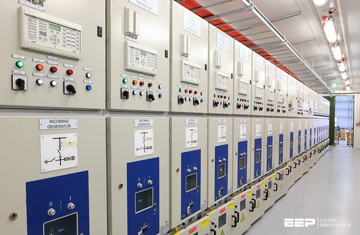
Microprocessors were introduced into substation products such as protection devices to improve the performance of the main product functions. Features such as improved accuracy and stability were delivered.
Communications ports were also incorporated, but these were more like a developer’s debug tool than the sophisticated ones we might recognise today.
Communication facilities developed, however. They were refined to provide connection to SCADA equipment to reduce hardwiring. Communications could provide operators with informative interfaces using software packages running on personal computers.
The digital substation brings major benefits in terms of design and engineering, installation, and operation. Off-the-shelf solutions can be offered, modifications can be easily accommodated, cabling (and hence costs), are reduced, and embedded diagnostics assure system integrity.
This article takes a tour through the enablers of the digital substation, looking at communications (and how to ensure that they are sufficiently secure, reliable, and dependable) concluding with an introduction to the standard IEC 61850.
- Communications
Communications
Communication is the conveyance of information from a source to a destination. In 1949 C. E. Shannon and W. Weaver produced a mathematical model for communications as shown in Figure 1.


The model shows that for the information to transfer from the source to the destination, a transmitter (encoder) and a receiver (decoder), both connected by a channel are required.
It also demonstrates that sources of noise can interfere with the process. Considering communication between two people, the source is the brain of the person who wants to get the message across, the transmitter could be that person’s voice and the channel is the atmosphere.
At the receiving end, the receiver would be the other person’s ears and the destination that person’s brain. Audible noise could drown out the message causing it not to be received and this is a possible cause of communication breakdown, but it is not the only one.
Similarly, if the two people talking don’t share a common language, and/or if certain protocols are not observed (e.g. not both speaking at the same time), failure is inevitable. Successful communication requires common understanding between source and destination.
1. The OSI Model for Computer Communications
In the context of substation automation, communication is the transfer of information from one computing device to another but, as with the example above, problems with synchronisation, language, and protocol can all cause communication failure.
The substation communication might be in the form of a dedicated link between two devices, or it may be over some form of communications network.
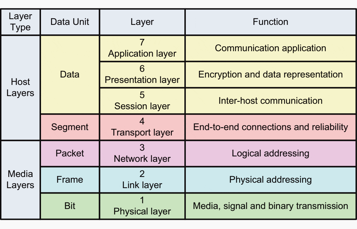
The International Standards Organisation (ISO) recognised the need for a framework for inter-device data communications, and in 1984 introduced the Open Systems Interconnection (OSI) model.
A model representing the seven layers is shown in Figure 2 with the purpose of the different layers being described below.

1.1 OSI Layer 1 – The Physical Layer
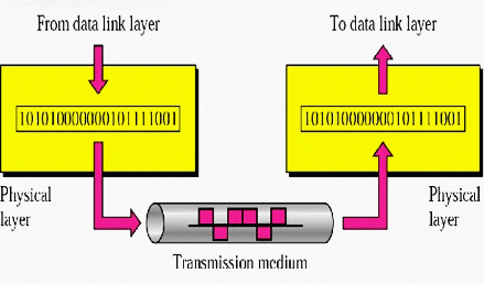
Every data message is transmitted on some medium. This medium usually takes the form of cables, wires, or optical fibres, but it could just as well be wireless, with the data being carried on electromagnetic waves.
A very common medium, particularly in Ethernet systems started with the CAT 5 UTP cable (Category 5 Unshielded Twisted Pair), which consists of four colour-coded twisted pairs of wires terminated with RJ45 connectors. As the name implies, this type of cable is not shielded against electromagnetic interference.
There is also a version of this cable called CAT 5 STP (Category 5 Shielded Twisted Pair) that has a metallic outer sheath, providing electromagnetic shielding. This type of cable is often used in noisy environments like the substation.
CAT 5, has more recently evolved into new standards such as CAT 6 and CAT 7, which offer even more robust shielding, fire protection etc.

1.2 OSI Layer 2 – The Data Link Layer
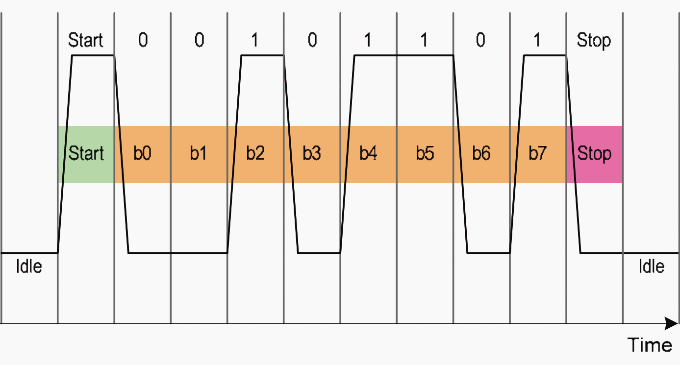
The physical layer provides the Data Link layer with bits. The Data Link layer now provides some intelligence to this sequence of bits by defining Data Frames. These Data Frames are packets of data containing the data to be transmitted and some control information governing the transmission.
An example is given in Figure 3 below.

A commonly used Data Link protocol is Ethernet. Examples of equipment that work at this layer are Ethernet switches and bridges.
1.3 OSI Layer 3 – The Network Layer
The network layer is concerned with packet delivery. Logical paths are established between the sending and receiving equipment by adding information onto the data frame which defines where the packet has come from, and where the packet is going to.
This takes the form of a logical source and destination address for each packet of information. A commonly used Network protocol is IP (Internet Protocol).
An example of equipment that operates at the network layer is a router.
1.4 OSI Layer 4 – The Transport Layer
The transport layer is the first layer that is not concerned with the mechanics of the data transfer. It is concerned with managing and sequencing the packets once they have arrived.
An example of a simple protocol is UDP (User Datagram Protocol). A more sophisticated widely used transport layer protocol used is TCP (Transmission Control Protocol).
Layer 4 functionality is achieved by the devices at either end of the transmission path, which is usually a computer. In the context of substation protection, this would be the IED.
1.5 OSI Layer 5 – The Session Layer
The first four layers establish a means of reliable communication between two IEDs (computers), but they do not deal with intelligent management of the communication.
This is performed at the session layer. It is the first layer that has user interaction. Each communication session is governed by criteria pertinent to the session. One communication session may be downloading a file from a web site, whilst another may be working on a file situated on a remote server.
Session layer software can implement password control, monitor system usage, and allow a user interaction with the communication.
1.6 OSI Layer 6 – The Presentation Layer
As the name implies, the presentation layer concerns itself with how the data is presented. A good example of this is ASCII (American Standard Code for Information Interchange).
An ASCII code is an 8-bit binary code, which defines the familiar character set used to produce text. For example the character ‘A’ is defined by the binary code 01000001, which is 41 hexadecimal or 65 decimal.
The presentation layer, if compliant with the ASCII format, can interpret this.
1.7 OSI Layer 7 – The Application Layer
The application layer is the layer that interacts with the user. This is in the main software that allows the user to define the communication.
2. Communications Between IEDs
The OSI model outlines the need for compatibility between all communication layers between computers (which are generally in the form of IEDs in the substation).
This section explores the lowest two layers: the physical and data link layers.
2.1 Physical Connection to IEDs for Substation
Control and Automation In substation control and automation systems, connection to IED communications ports at the physical layer (OSI layer 1) is generally to one of three standards:
- EIA 232
- EIA 485
- Ethernet
EIA (Electronic Industries Association) is a set of standards defined for connecting electronic devices together. They were formerly known as the recommended standards (RS) and often people will still refer to them as RS 232 and RS 485.
NOTE! Although, traditionally the standards were designed with metallic connections between devices, more recent times have seen an increase in optical fibre as the medium connecting networks and devices. Any of the physical layer and data link layer protocols have now been modified to work over optical fibre as well.
2.1.1 EIA 232 (ex RS 232)
EIA 232 is an electrical connection allowing full duplex communication between two devices. Prior to the development of the USB port, it was the typical serial port found on most computers and is characterised by Table 24.1
Table 1 – EIA(RS)232 characteristics
| Item | Details |
| Max. number of transmitters | 1 |
| Max. number of receivers | 1 |
| Connection type | 25 core shielded |
| Mode of operation | DC coupling |
| Maximum distance of transmission | 15m |
| Maximum data rate | 20kbits/s |
| Transmitter voltage | 5V min, 15V max |
| Receiver intensity | 3V |
| Driver slew rate | 30V/μs |
EIA 232 was designed to allow computers to connect using Modems and is suitable only for point-to-point connection. It uses switched single-sided 12V (nominal) signals for data transmission as well as handshake signals to control the communication.
For permanent connection in a substation environment, the use of optical isolating units should be considered to avoid damage caused by induced transients.
If transmission over longer distances is required, some form of EIA 232 to fibre-optic converter and a fibre-optic communications link should be used.
Since EIA 232 provides only point to point connectivity it is not used in automation systems, rather it is limited to relaying information to a SCADA system.
2.1.2 EIA 485
EIA 485 is an electrical connection characterised by Table 2 below.
Table 2 – EIA(RS)485 characteristics
| Item | Details |
| Max. number of transmitters | 32 |
| Max. number of receivers | 32 |
| Connection type | Shielded twisted pair |
| Mode of operation | Differential |
| Maximum distance of transmission | 1200m |
| Maximum data rate | 10Mbits/s |
| Transmitter voltage | 1.5V min |
| Receiver intensity | 300mV |
EIA 485 provides a two-wire half-duplex connection designed for multi-drop connections as shown in Figure 4 which makes it more suitable than EIA 232 for use in automation schemes.


EIA 485 uses differential signalling on twisted pairs and can be isolated. The multi-drop connection (sometimes called daisy-chaining) generally has a limit of 1km, and although in theory the number of devices connected (nodes) is not limited, a practical limit is normally 32 per bus, with repeaters being
used if further expansion is required.
Communication speeds of 64kbits per second (kbps) can be reliably achieved. EIA 485 allows relatively simple networks to be constructed very efficiently and cost effectively.
2.1.3 Ethernet
Ethernet is a standard, which defines the connection of computing devices to local area networks (LANs). As per IEEE 802.3, standard signalling speeds are 10Mbps, 100Mbps or 1Gbps. It is the most widespread LAN technology.
The specification allows connection to be made either electrically using an RJ45 connector, or by direct fibre-optic connection.
Ethernet over fibre-optic cables provide a mechanism for extremely high speed and noise resistant communication, making it the ideal communication medium for the substation.
2.2 Network Topologies
When linking multiple products together to form a computer network, in addition to the physical connection of the device, it is also necessary to consider the network topology as well as the protocol or language by which information is exchanged.
In early centralised systems, a hierarchical series of connections is required for devices at the acquisition and process levels to communicate data upwards and to receive commands in return. This tree-type structure typifies the kind of connection that the point-to-point EIA 232 communications can bring.
The multi-drop capabilities of EIA 485 do more to encourage distribution of control since the EIA 485 network will have devices connected on the same multi-drop bus, with a master connected to many slaves.
Systems based on Ethernet technology provide more scope for different topologies by virtue of equipment such as switches, hubs, bridges and routers.
2.3 Serial Communications
This is a form of communication whereby bits of data are exchanged serially through the signalling channel. With parallel communications multiple bits of data are exchanged in parallel.
An example of parallel communication is the LPT printer port that used to feature on computers, printers, and office equipment before the widespread deployment of Ethernet in the working environment.
This article adheres to that convention and continues with a discussion on “serial” communications based on EIA 232 and EIA 485, later followed by Ethernet communication.
2.3.1 Serial Communications Protocols
A communications protocol is a set of standard rules for data representation, signalling, authentication and error detection, which defines the transfer of information over a communication channel.
Put another way, for devices to be able to speak to each other, they need to share a common language and rules of engagement.
When digital communication facilities were first added to computer based protection devices, no standard protocol existed for this communication. Manufacturers developed their own proprietary solutions to exploit the benefits of the communication interfaces.
Consider a relatively simple system, with a bay controller connected to IEDs from different manufacturers A, B, and C as depicted in Figure 5.
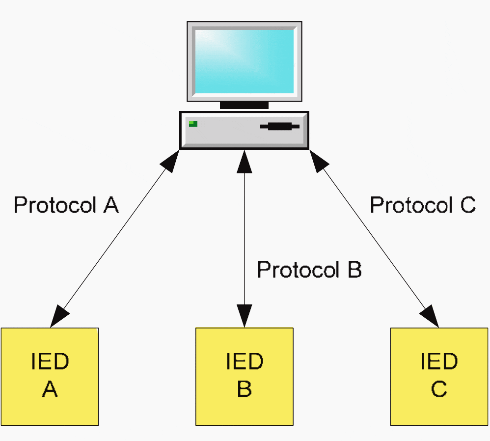

If the three products all contain key elements to implement the control system, then either the bay controller would need to support three communications protocols (as shown in the figure), or some form of protocol converter devices would need to be included.
Efforts were made to develop a standard solution and from the protocols available, three open standards for IED serial communications emerged:
- MODBUS
- IEC 60870-5-103
- DNP3
Modbus
Modbus was published in 1979 by Modicon. Originally designed for programmable logic controllers of the time, it is a master-slave protocol that allows a master
to read or write bits in registers of the slave devices.
It can be implemented on simple serial connections (EIA 485), but has also been migrated to Ethernet.
IEC 60870-5-103
IEC 60870-5-103 was developed by Technical Committee 57 of the International Electro-technical Committee (IEC TC57). It is based on, and is a superset of, the German VDEW communications standard.
As well as simple electrical connection, the standard also defines a direct communication interface implemented over optical fibre.
DNP3
DNP3 was developed by Harris in the 1990s. It drew on early work of TC57 on the IEC 60870-5 (before it was standardised) to develop something with a specific focus on the North American market that could be quickly implemented.
Like Modbus, it is also supported on Ethernet as well as simple serial connection.
Although originally targeted at the North American market, it has been deployed elsewhere. The use of these open communications standards simplified the system engineering, making future upgrading and expansion easier, hence reducing overall life-cycle costs.
In general, the open standards of Modbus, IEC60870-5-103 and DNP3 cover layers 1-4 of the OSI model. They allow automation systems engineers to mix and match IEDs from different manufacturers with the same protocol, satisfying the clients’ needs for protection and control better than if a mix of proprietary protocols were used.
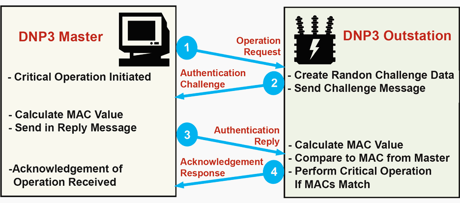

Each of the protocols has particular advantages, but they all suffer disadvantages too:
- Although they are standard protocols, all have ambiguities that result in different implementations in different IEDs.
- The IED data model (i.e. the way the data representing the IED is structured and presented over the communications link) varies between vendors, and can sometimes vary between different versions of the same IED from the same vendor.
- Different functionalities are supported by the different protocols, and different IED vendors may support different levels of those functionalities.
- The provision of private codes in the IEC 60870-5-103 protocol permits much greater functionality, but at the same time hinders interoperability of equipment from different vendors because there is no need for the format of such messages to be made public. In effect, the use of ‘private’ messages by vendors of devices essentially turns the standard into several proprietary ones.
Due to continuing developments in the fields of computing and communications, there is a need for a truly open communications architecture allowing ‘plug-and-play’ connectivity between devices from different manufacturers for effective, efficient substation automation.
The IEC61850, standard, based on Ethernet satisfies that need.
2.4 Ethernet Communications
Ethernet defines the connection of computing devices to local area networks (LANs). It is the most widespread LAN technology.
Standardised in IEEE 802.3, it describes the requirements for network connection according to layer 1 (the physical layer) and layer 2 (the data link layer) of the OSI model.
Standard signalling speeds for Ethernet communications are 10Mbps, 100Mbps, 1Gbps and 10Gbps.
The most commonly used network protocol (layer 3 of the OSI model) is the Internet Protocol (IP), and the most commonly used transport layer mechanism (OSI layer 4) is the Transmission Control Protocol (TCP). Often these are put together as ‘TCP/IP’ and are synonymous with Ethernet and the internet.
At the network layer, IP is used to transfer packets of data on the network and across network boundaries from the source to the destination.
To do this, devices are assigned IP addresses and these addresses have two purposes:
The first is to identify the host network (which may be subdivided into subnetworks), whilst the second is to identify the device on the network or sub-network (subnet). The IP address is a 32 bit binary number, which can be written in the form nnn.nnn.nnn.nnn, where nnn represents a binary octet, and is an integer value between 0 and 255.
A typical IP address is, therefore, 192.168.0.2. Each device on the network will have an IP address that is unique and may be configured by a network server, a system administrator, or by an address auto-configuration.
Typically the two most significant octets identify the network. The two least significant octets are used for device identification, but can also be used to create subnets. A so called subnet mask is then used to identify the subnet address.
For example if the third octet were used as a subnet identifier, then performing a logical AND between the IP address and 255.255.255.0 (the subnet mask) would identify that, in the case above, the subnet address is 192.168.0.0 and the device is at address 2 on that subnet. When a packet of data is placed on the IP network, it is sent to its destination network by means of routers, switches and hubs.
4.5 IEC 61850
In the early 1990s the Electric Power Research Institute (EPRI) in the US started work on a Utility Communications Architecture (UCA). The goal was to produce industry consensus regarding substation integrated control, protection, and data acquisition, to allow interoperability of substation devices from different manufacturers.
The work developed to produce UCA2 which showed that true interoperability was possible. UCA2 was taken forward by IEC TC57 to produce the standard IEC61850 that revolutionises substation automation.
4.5.1 Benefits of IEC 61850
IEC 61850 is the international standard for Ethernet-based communication in substations. It enables integration of all protection, control, measurement and monitoring functions within a substation, and additionally provides the means for interlocking and inter-tripping.
Some of the key features and capabilities of IEC 61850 are as follows:
- Use of a virtualised model: In addition to the protocols that define how the data is transmitted over the network, the virtualised model also allows definition of data, services, and device behaviour.
- Use of names for data: Every element of IEC 61850 data is named using descriptive strings.
- Object names are standardised: Names are not dictated by the device vendor nor configured by the user. They are defined in the standard and provided in a power system context, which allows the engineer to immediately identify the meaning of the data.
- Devices are self-describing: Client applications can download the description of all the data, without any manual configuration of data objects or names.
- High-Level Services: IEC61850’s abstract communications service interface supports a wide variety of services, such as generic object-oriented substation events (GOOSE), sampled measured values (SMV), logs, etc.
- Standardised substation configuration language (SCL): SCL enables the configuration of a device and its role in the power system to be precisely defined using extensible mark-up language (XML) files.
The major benefits of the standard are as follows:
- Eliminates procurement ambiguity: As well as for configuration purposes, SCL can be used to precisely define user requirements for substations and devices.
- Lower installation cost: IEC 61850 enables devices to exchange data using GOOSE over the station LAN without having to wire separate links for each IED.
By using the station LAN to exchange these signals, this reduces infrastructure costs associated with wiring, trenching and ducting.
- Lower transducer costs: A single merging unit can deliver measurement signals to many devices using a single transducer. This reduces transducer, wiring, calibration, and maintenance costs.
- Lower commissioning costs: IEC 61850-compatible devices do not require much manual configuration. Also, client applications do not need to be manually configured for each point they need to access, because they can retrieve this information directly from the device or import it via an SCL file.Many applications require nothing more than the setting up of a network address. Most manual configuration is therefore eliminated, drastically reducing errors, rework, and therefore costs.
- Lower equipment migration costs: The cost associated with equipment migrations is reduced due to the standardised naming conventions and device behaviour.
- Lower extension costs: Adding devices and applications into an existing IEC 61850-based network can be done with little impact on existing equipment.
- Lower integration costs: IEC 61850 networks are capable of delivering data without separate communication front-ends or reconfiguring devices. This means that the cost associated with integrating substation data is substantially reduced.
- Implement new capabilities: IEC61850 enables new and innovative applications that would be too costly to produce otherwise.This is because all data associated with a substation is available on its LAN in a standard format and accessible using standard protocols.
4.5.6 IEC61850-9.2
In IEC61850-9.2, the wiring that traditionally connected transformers and switchgear to protection control and monitoring devices is replaced by a process bus, where the process bus is a high-speed Ethernet communications network.
Merging units form the data acquisition layer in the network and present sampled measured values to IEDs via the process bus.
The interface of the merging unit with the primary plant may either be in the form of conventional transformers, or with non-conventional instrument transformers (NCIT), but the output is the same: time-stamped sampled measured values.
These later-life costs include any need for extension, upgrade or retrofitting, and also any periodic maintenance.
4.6 Conclusion
IEC61850-9.2, and IEC61850 in general are at the heart of the digital substation. Together they have revolutionised substation engineering.
This article has aimed to equip engineers with an understanding of the terminology and concepts in order to be able to function in this new world focused on Ethernet communication technology.
Reference // Network protection and and automation guide by Alstom Grid




Hi,
I am so delighted to read your articles for these years. I just want to commend you for the good work that you are doing.
Thanks
Great introduction to 61850, and provided an appropriate level of background info and context.
Loved the links to the supplemental videos!
Very good for article .Useful and nice presentation.
Thank you Shivakumar.
I am fresher for in Bachelor of Electrical Engineering in 2019 ,this is my first job in career, so I am very excited in my professional field in electrical designings.
Good article. keep sharing….
Great article I learnt a lot from this article.
Great article which provides a clear and concise explanation.
Thanks for sharing this information with us. After read this article we know about “The OSI Model for Computer Communications”. Keep sharing.
Thanks ?,for your article.
excelent work, i wuld like that you talk abaout communications wiht optical fiber and theirs protocols.