
Introduction to transducer
The accurate measurement of the voltage, current or other parameter of a power system is a prerequisite to any form of control, ranging from automatic closed-loop control to the recording of data for statistical purposes. Measurement of these parameters can be accomplished in a variety of ways, including the use of direct-reading instruments as well as electrical measuring transducers.
There are a wide range of measurement devices used to collect data and convert it into useful information for the operator. Generally, the devices are classified as to whether the measurements are to be used locally or remotely.
- Local Information: by instruments or meters which (directly connected, or via a transducer), and measurement centres
- Transmitted Data: by transducers
- Remote Systems: by measurement centres, disturbance recorders or power quality recorders
- General transducer characteristics
- Digital Transducer Technology
- Analogue Transducer Technology
- Transducer Selection
1. General transducer characteristics
Transducers produce an accurate d.c. analogue output, usually a current, which corresponds to the parameter being measured (the measurand). They provide electrical isolation by transformers, sometimes referred to as ‘Galvanic Isolation’, between the input and the output. This is primarily a safety feature, but also means that the cabling from the output terminals to any receiving equipment can be lightweight and have a lower insulation specification.
The advantages over discrete measuring instruments are as follows:
- Mounted close to the source of the measurement, reducing instrument transformer burdens and increasing safety through elimination of long wiring runs
- Ability to mount display equipment remote from the transducer
- Ability to use multiple display elements per transducer
- The burden on CTs/VTs is considerably less
Whatever measurement transducer is being used, there will usually be a choice between discrete and modular types, the latter being plug-in units to a standard rack. The location and user-preferences will dictate the choice of transducer type.
1.1 Transducer Inputs
The input of a transducer is often taken from transformers and these may be of many different types. Ideally, to obtain the best overall accuracy, metering-class instrument transformers should be used since the transformer errors will be added, albeit algebraically, to the transducer errors.
However, it is common to apply transducers to protection-class instrument transformers and that is why transducers are usually characterised to be able to withstand significant short-term overloads on their current inputs.
A typical specification for the current input circuits of a transducer suitable for connection to protection-class instrument transformers is to withstand:
- 300% of full-load current continuously
- 2500% for three seconds
- 5000% for one second
The input impedance of any current input circuit will be kept as low as possible, and that for voltage inputs will be kept as high as possible. This reduces errors due to impedance mismatch.
1.2 Transducer Outputs
The output of a transducer is usually a current source. This means that, within the output voltage range (compliance voltage) of the transducer, additional display devices can be added without limit and without any need for adjustment of the transducer. The value of the compliance voltage determines the maximum loop impedance of the output circuit, so a high value of compliance voltage facilitates remote location of an indicating instrument.
The constant current nature of the transducer output simply raises the voltage and continues to force the correct output signal round the loop.
1.3 Transducer Accuracy
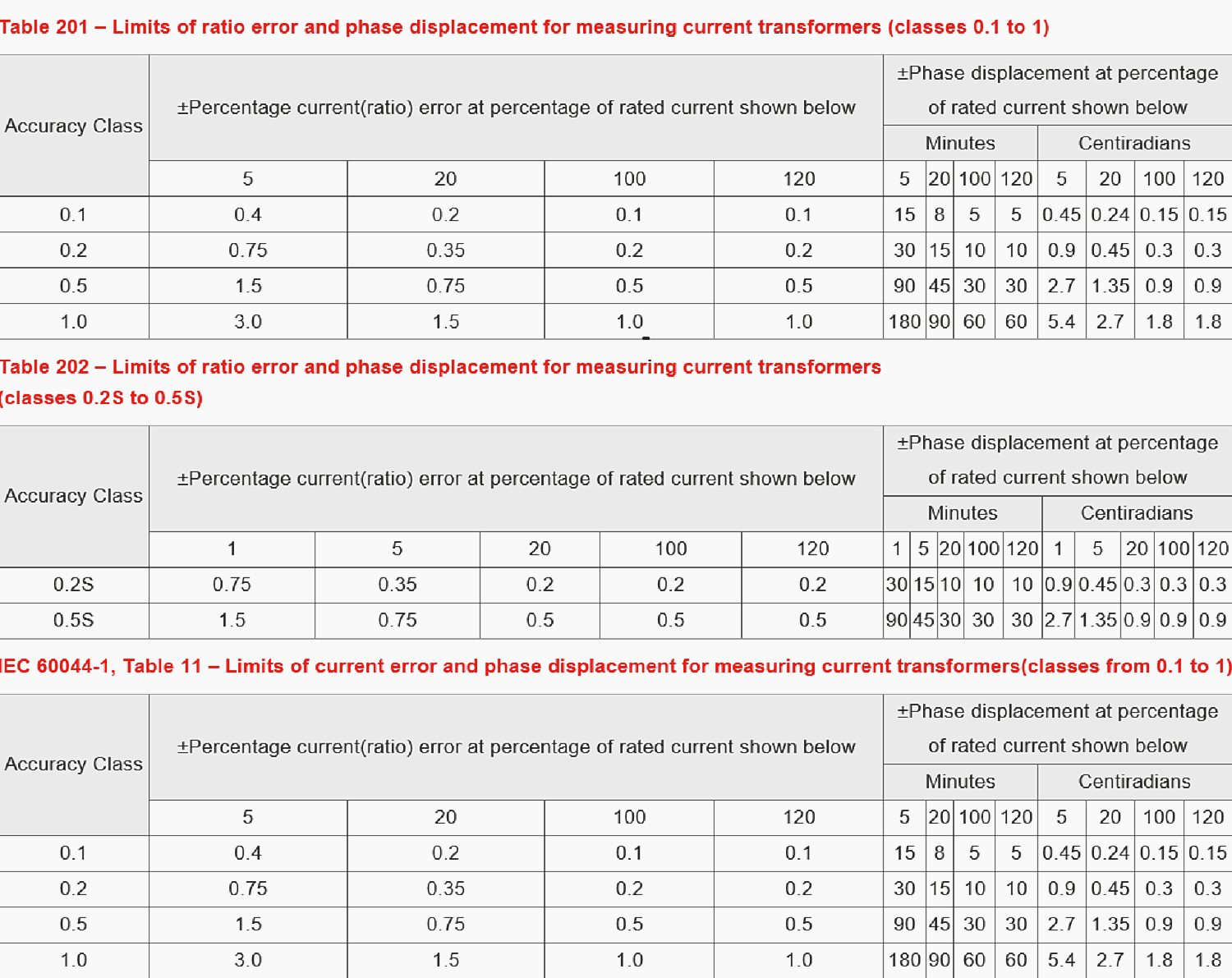
Accuracy is usually of prime importance, but in making comparisons, it should be noted that accuracy can be defined in several ways and may only apply under very closely defined conditions of use. The following attempts to clarify some of the more common terms and relate them to practical situations, using the terminology given in IEC 60688.
The accuracy of a transducer will be affected, to a greater or lesser extent, by many factors, known as ‘influence quantities’, over which the user has little, or no, control.
Table 1 – Overall product accuracy requirements for energy monitoring, metering for energy conservation and revenue purposes
2. Digital transducer technology
Digital power system transducers make use of the same technology as that described for digital and numerical relays in this article. The analogue signals acquired from VTs and CTs are filtered to avoid aliasing, converted to digital form using A/D conversion, and then signal processing is carried out to extract the information required.
Sample rates of 64 samples/cycle or greater may be used, and the accuracy class is normally 0.2 or 0.5. Outputs may be both digital and analogue. The analogue outputs will be affected by the factors influencing accuracy as described above.
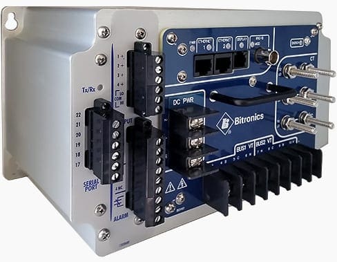
Digital outputs are typically in the form of a communications link, with RS232 or RS485 serial, and RJ45 Ethernet connections commonly available.
The advantages of a transducer using numerical technology are:
- Improved long-term stability
- More accurate r.m.s measurements
- Improved communications facilities
- Programmability of scaling
- Wider range of functions
- Reduced size
The improved long term stability reduces costs by extending the intervals between re-calibration. More accurate r.m.s measurements provide the user with data of improved accuracy, especially on supplies with significant harmonic content.
The improved communications facilities permit many transducers to share the same communications link, and each transducer to provide several measurements.
It also minimizes the risk of the user specifying an incorrect scaling factor and having to return the transducer to the manufacturer for adjustment. Suppliers can keep a wider range of transducers suitable for a wide range of applications and inputs in stock, thus reducing delivery times.
Transducers are available with a much wider range of functions in one package, thus reducing space requirements in a switchboard. Functions available include harmonics up to the 31st, energy, and maximum demand information. The latter are useful for tariff negotiations.
3. Analogue transducer technology
All analogue transducers have the following essential features:
- An input circuit having impedance Zin
- Isolation (no electrical connection) between input and output
- An ideal current source generating an output current, I1, which is an accurate and linear function of Qin, the input quantity
- A parallel output impedance, Zo. This represents the actual output impedance of the current source and shunts a small fraction, I2, of the ideal output
- An output current, Io, equal to (I1 – I2)
These features are shown diagrammatically in Figure 22.1.
Output ranges of 0-10mA, 0-20mA, and 4-20mA are common. Live zero (e.g. 4-20mA), suppressed zero (e.g. 0-10mA for 300-500kV) and linear inverse range (e.g. 10-0mA for 0-15kV) transducers normally require an auxiliary supply.
The dual-slope type has two linear sections to its output characteristic, for example, an output of 0-2mA for the first part of the input range, 0-8kV, and 2-10mA for the second part, 8-15kV.
4. Transducer Selection
The selection of the correct transducer to perform a measurement function depends on many factors. These are detailed below.
4.1 Current Transducers
Current transducers are usually connected to the secondary of an instrument current transformer with a rated output of 1 or 5 amps. Mean-sensing and true r.m.s. types are available. If the waveform contains significant amounts of harmonics, a true r.m.s sensing type must be used for accurate measurement of the input.
They can be self-powered, except for the true r.m.s. types, or when a live zero output (for example 4-20mA) is required. They are not directional and, therefore, are unable to distinguish between ‘export’ and ‘import’ current.
To obtain a directional signal, a voltage input is also required.

4.2 Voltage Transducers
Connection is usually to the secondary of an instrument voltage transformer but may be direct if the measured quantity is of sufficiently low voltage. The suppressed zero type is commonly used to provide an output for a specific range of input voltage where measurement of zero on the input quantity is not required.
The linear inverse type is often used as an aid to synchronising.
4.3 Frequency
Accurate measurement of frequency is of vital importance to transmission system operators but not quite so important, perhaps, for the operator of a diesel generator set. Accuracy specifications of 0.1% and 0.01% are available, based on percent of centre scale frequency.
This means, for example that a device quoted as 0.1% and having a centre scale value of 50Hz will have a maximum error of +/- 50mHz under reference conditions.
4.4 Phase Angle
Transducers for the measurement of phase angle are frequently used for the display of power factor. This is achieved by scaling the indicating instrument in a non-linear fashion, following the cosine law. For digital indicators and SCADA equipment, it is necessary for the receiving equipment to provide appropriate conversions to achieve the correct display of power factor.
Transducers are also available for the measurement of the angle between two input voltages. Some types of phase angle transducer use the zero crossing point of the input waveform to obtain the phase information and are thus prone to error if the input contains significant amounts of harmonics.
Calculating the power factor from the values of the outputs of a watt and a var transducer will give a true measurement in the presence of harmonics.
4.5 Power Quantities
The measurement of active power (watts) and reactive power (vars) is generally not quite as simple as for the other quantities. More care needs to be taken with the selection of these types because of the variety of configurations.
It is essential to select the appropriate type for the system to be measured by taking into account factors such as system operating conditions (balanced or unbalanced load), the number of current and voltage connections available and whether the power flow is likely to be ‘import’, ‘export’, or both.
The range of the measurand will need to encompass all required possibilities of over-range under normal conditions so that the transducer and its indicating instrument, or other receiving equipment, is not used above the upper limit of its effective range. Figure 22.2 illustrates the connections to be used for the various types of measurement.
4.6 Scaling
The relationship of the output current to the value of the measurand is of vital importance and needs careful consideration. Any receiving equipment must, of course, be used within its rating but, if possible, some kind of standard should be established.
Example
As an example, examine the measurement of AC voltage. The primary system has a nominal value of 11kV and the transformer has a ratio of 11kV/110V. To specify the conversion coefficient for the voltage transducer to be 110V/10mA would not necessarily be the optimum. One of the objectives must be to have the capability of monitoring the voltage over a range of values so an upper limit must be selected – for instance +20%, or 132V. Using the original conversion coefficient, the maximum output of the transducer is required to be 12mA.
This is within the capability of most 0-10mA transducers, the majority of which can accommodate an over-range of 25%, but it does mean any associated analogue indicating instrument must have a sensitivity of 12mA.
However, the scale required on this instrument is now 0-13.2kV, which may lead to difficulty in drawing the scale in such a way as to make it readable (and conforms to the relevant standard). In this example, it would be more straightforward to establish the full-scale indication as 15kV and to make this equivalent to 10mA, thus making the specification of the display instrument much easier.
Such outputs are typically used as inputs to SCADA systems, and the SCADA system is normally programmed to assume that a current magnitude in excess of 20mA represents a transducer failure. In addition, a reading below 4mA also indicates a failure, usually an open circuit in the input connection.
Thus, using the above example, the output might be scaled so that 20mA represents 132V and hence the nominal 110V input results in an output of 16.67mA. A more convenient scaling might be to use 16mA as representing 110V, with 20mA output being equal to 137.5V (i.e. 25% over-range instead of the 20% required).
It would be incorrect to scale the transducer so that 110V input was represented by 20mA output, as the over-range capability required would not be available.
Similar considerations apply to current transducers and, with added complexity, to watt transducers, where the ratios of both the voltage and the current transformers must be taken into account. In this instance, the output will be related to the primary power of the system.
It should be noted that the input current corresponding to full-scale output may not be exactly equal to the secondary rating of the current transformer but this does not matter – the manufacturer will take this into account. Some of these difficulties do not need to be considered if the transducer is only feeding, for example, a SCADA outstation. Any receiving equipment that can be programmed to apply a scaling factor to each individual input can accommodate most input signal ranges.
The main consideration will be to ensure that the transducer is capable of providing a signal right up to the full-scale value of the input, that is, it does not saturate at the highest expected value of the measurand.
Recommended reading:
Voltage and current measurement in modern digital high voltage substations
4.7 Auxiliary Supplies
Some transducers do not require any auxiliary supply. These are termed ‘self-powered’ transducers. Of those that do need a separate supply, the majority have a biased, or live zero output, such as 4-20mA. This is because a non-zero output cannot be obtained for zero input unless a separate supply is available.
For AC measuring transducers, the use of a DC auxiliary supply enables the transducer to be operated over a wider range of input. The range of auxiliary supply voltage over which a transducer can be operated is specified by the manufacturer. If the auxiliary voltage is derived from an input quantity, the range of measurement will be restricted to about +/-20% of the nominal auxiliary supply voltage.
This can give rise to problems when attempting to measure low values of the input quantity.
Source: Alstom Grid


It is very good information.