Contents
- Dimensioning of neutral conductor
- Neutral conductor disconnection
- Neutral conductor protection
- Equipment for disconnecting and protecting the neutral
1. Dimensioning of neutral conductor
In sinusoidal operation, the current in the neutral conductor is determined by the unbalance between the single-phase loads connected between phases and neutral.
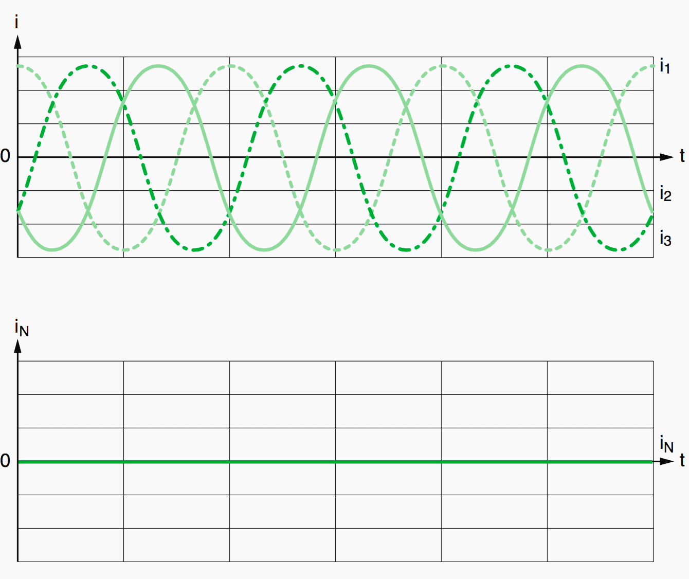
- Balanced loads: The current in the neutral conductor is zero (see Fig. 1 ).
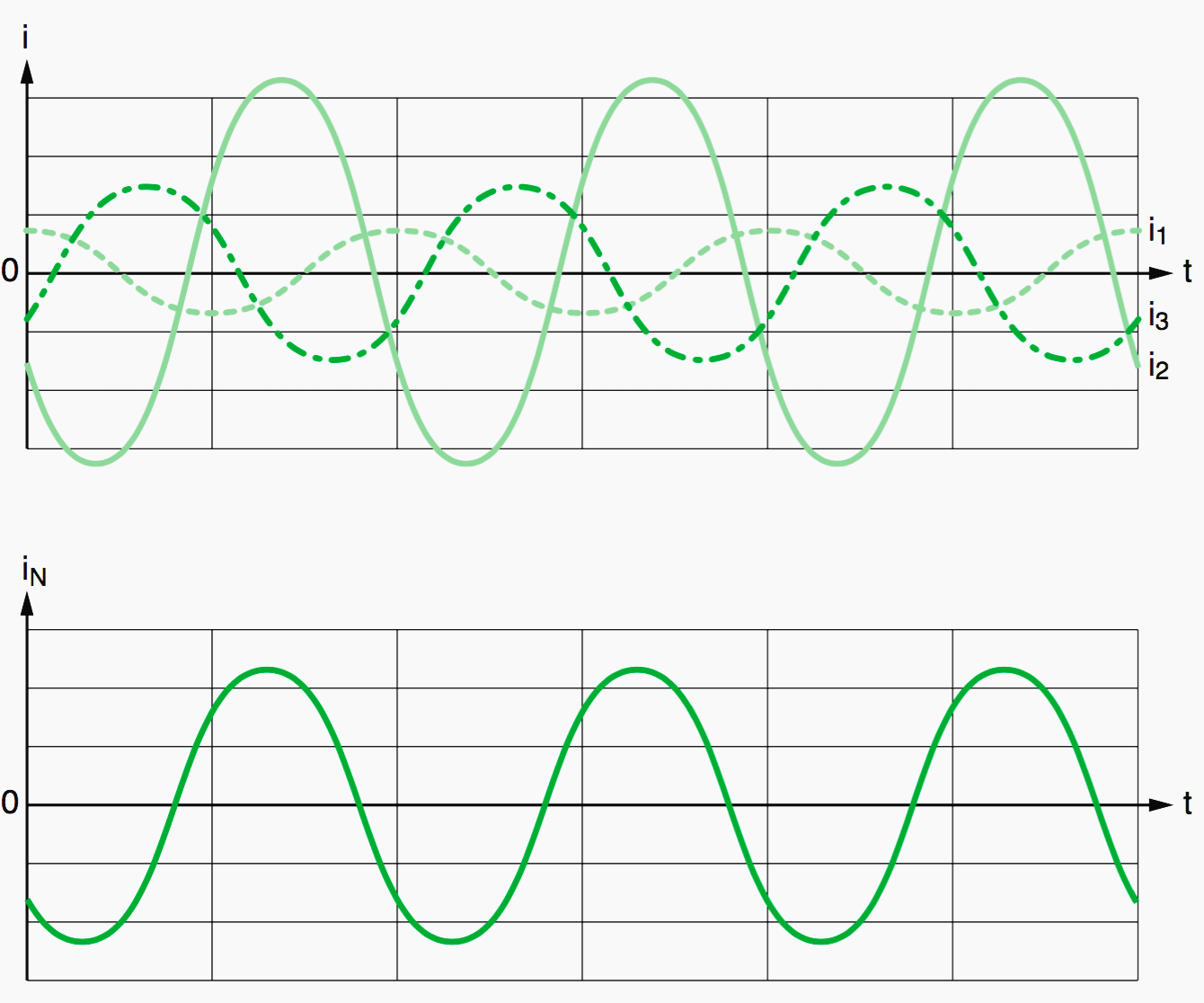
- Unbalanced loads: The current in the neutral conductor is not zero, as illustrated in Figure 2.
In the event of unbalanced loads of the same type, the current in the neutral conductor is less than or equal to the highest phase current (see Fig. 3). In the event of unbalanced loads of different types on each phase (resistive, inductive, capacitive), the neutral current may be greater than the current in each of the phases. However, this scenario is rare in practice.
The cross-sectional area of the neutral conductor, defined as a function of the current conducted, may be:
Smaller than the cross-sectional area of the phase conductors…
Smaller than the cross-sectional area of the phase conductors if the following conditions are met simultaneously:
- The cross-sectional area of the phase conductors must be greater than 16 mm2 (copper) or 25 mm2 (aluminum).
- The cross-sectional area of the neutral conductor must be at least equal to 16 mm2 (copper) or 25 mm2 (aluminum).
- The loads supplied with power during normal operation are assumed to be balanced, with a third harmonic ratio of less than 15%.
- The neutral conductor must be protected against overcurrents.

A common technique is to use a neutral conductor with a cross-sectional area “half” that of the cross-sectional area of the phase conductors.
Equal to the cross-sectional area of the phase conductors
This is the general case, in particular in single-phase circuits with 2 conductors, or when the cross-sectional area of the phase conductors is less than 16 mm2 (copper) or 25 mm2 (aluminum). It is equally true in the case of power supplies for non-linear loads and if the third harmonic ratio is located in the range between 15 and 33%.

Greater than or equal…
Greater than or equal to the cross-sectional area of the phase conductors in the event of power supplies for non-linear loads and if the third harmonic ratio is greater than 33%. The current in the neutral conductor is therefore a key factor in determining the cross-sectional area of the conductors.
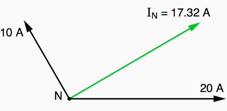
An unbalanced current circulates on a three- phase line supply due to the impossibility of achieving a permanent and perfect balance between the single-phase loads. This current is equal to:
IN = I1 + I2 + I3
It may be very variable, as shown in the example below.
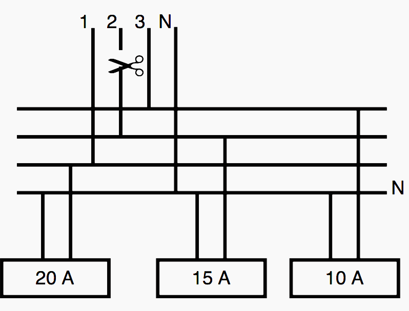


It may even be greater than the phase current if phase 2 is disconnected:

2. Neutral conductor disconnection
The rules for the disconnection or maintaining of the neutral conductor are designed to limit the risks of electrocution, which accompany an increase in potential.
TN-C system
The neutral conductor is also the protective earth (called PEN). It is therefore essential that its continuity is maintained under all circumstances. For this reason, no breaking devices may be connected to it.
TT or TN-S system
The neutral is earthed at the installation supply point. Under normal conditions, its potential is similar to the earth potential. However, for a variety of reasons, the potential of the neutral conductor may deviate significantly from the earth potential and reach dangerous voltages in relation to earth.
A possible scenario is illustrated in Figure 4. The current circulating in the neutral conductor causes the neutral potential to increase on one load, even if this load is not connected to the phase following an operation or a trip.
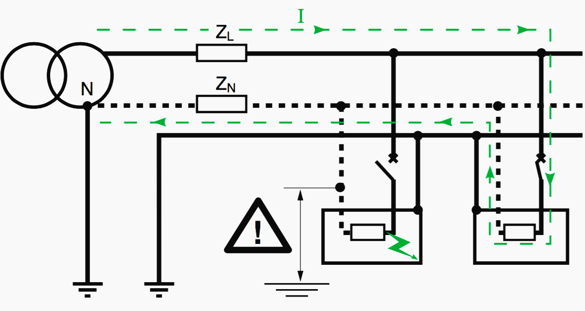

Moreover, as cable inversion between phase and neutral on one load is always a possibility, the non-breaking of one of the polarities actually risks the phase voltage applied to the load being maintained.
In addition, in the event of a fault in one part of the installation (accidental disconnection of neutral conductor upstream, increase in impedances, MV/LV fault, lightning strike on low- voltage lines, etc.), the potential of the neutral for user loads may rise abruptly to reach dangerous levels.
These risks are particularly inherent on the floors of multi-storey buildings, where it is more difficult to ensure the quality of earthing systems due to the exceptionally long cables.
An extreme case in which the neutral potential in relation to earth was 80 V in normal operation has already been measured on one installation. This presents a risk of electrocution. In order to avoid creating dangerous situations, the stringent application of the neutral disconnection rule is strongly recommended.
IT system
The potential of the neutral conductor may be at any level, even if it is generally close to the earth potential. If a fault is pending (e.g. phase-to- earth), the potential of the neutral in relation to earth may increase until it reaches the level of the phase voltage.
Only by disconnecting the neutral is it possible to ensure that the potentials between the frame and earth will be equal following tripping.
Important recommendations
#1 – The neutral must never be disconnected alone!
It must be disconnected after the phases and reconnected before the phases. Failure to observe this rule will lead to overvoltages on single-phase devices in unbalanced three- phase operation, as the phase-to-phase voltage can be applied to a circuit designed to be supplied with power via the phase voltage (phase-to-neutral). This risk is illustrated in Figure 11.


If the load connected between phase 3 and neutral is much larger than the loads on the other phases (1 and 2), the artificial neutral point N’ will be set to a potential similar to that of phase 3 if the neutral conductor trips. The loads connected between phases 1, 2 and N’ will therefore be subject to voltages V1N’ and V2N’, close to V13 and V23.
In addition, due to the prevailing voltages, the breaking device for the neutral conductor will have to exhibit the necessary characteristics for isolation, in particular a sufficient insulation voltage (e.g. resistance to a 12.3 kV surge at LV for industrial equipment, in accordance with standard IEC 60947).
#2 – Neutral conductor to be blue and letter N
For the purpose of disconnection, the neutral must be clearly identifiable, which is why installation standards require the conductor to be light blue in color and terminals and diagrams to bear the letter N.
Note: In an electrical distribution system without neutral, the blue conductor can be used as a phase, although this is not recommended.
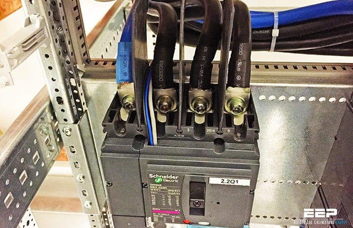
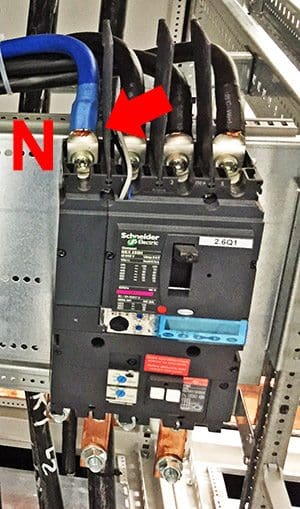
Requirements regarding the position of the neutral pole in the equipment are rarely prescribed in relevant standards, except for example in France in C 62-411 for LV incoming circuit breakers. However, it is common in many European countries, including France, to use neutral connection terminals to the left of the phase connection terminals (see Fig. 6).

3. Neutral conductor protection
TN-C system
As the protective earth (PE) cannot be disconnected under any circumstances, it is not possible to disconnect the conductor (N) in a TN-C type installation in which the two conductors are combined in one (PEN). Consequently, the cross-sectional area of the neutral will be selected accordingly since protection via automatic disconnection is not applicable.
TT or TN-S system
In the event of an overload or phase-neutral short-circuit on a given feeder, the same fault current will flow through the phase and neutral conductors. There are two possible scenarios:
- Cross-sectional area of the neutral equal to the cross-sectional area of the phases
Protection of the neutral is not obligatory. The neutral conductor is protected by the protective device for the phase conductor. - Cross-sectional area of the neutral smaller than the cross-sectional area of the phases
A protective device to guard against overloads dimensioned according to the cross-sectional area of the neutral conductor is obligatory.
IT system
Double faults (one on a phase and the other on the neutral), may affect feeders with different ratings (connected by the faults).
Protecting the individual phases is not an entirely reliable solution and here is the explanation:
The protection for a phase with a higher rating on one feeder may not be suitable for the cross-sectional area of the neutral on the other feeder. Provision for the protection and disconnection of the neutral is therefore obligatory, except in specific cases (e.g. single-phase circuits, protection via RCDs, etc.).
4. Equipment for disconnecting and protecting the neutral
If the above conditions have been fulfilled and if the neutral is clearly labeled, it is possible – even recommended for economical reasons – not to protect it. In all other cases, the risks of phase/ neutral inversion justify protecting the neutral conductor.
Fuses
Except in very specific cases (use of fuse cartridges with strikers connected to a breaking device), the blowing of a fuse located in a live conductor will not cut off the current in the other live conductors: the break is single-pole. In order to avoid only the neutral being disconnected, it must never be protected by a fuse.
Equally, the neutral conductor will not be disconnected automatically if a fuse on one of the phases blows.
Circuit breakers
2-pole (phase/phase or phase/neutral) or 4-pole circuit breakers can be used to disconnect the phases and the neutral simultaneously in order to cut off the power supply to a circuit.
Phase/neutral devices on which only the phase is protected are less expensive and more compact, although the neutral must be clearly labeled.


Residual current devices (RCDs)
RCDs are considered a very reliable means of ensuring the operation of an electrical installation. They help to protect against direct and indirect contact as well as providing protection against fire. Moreover, RCDs will continue to operate in the event of a phase/neutral inversion.
Because RCDs combine all these functions in a single device, their use is recommended both in new installations and in extensions to existing installations.
Emergency breaking devices
In order to ensure that the power supply to a circuit can be cut off quickly, multi-pole breaking (of all live conductors including the neutral) is recommended via the breaking device or emergency stop.
Control and monitoring
However, when auxiliary contacts on protective devices are used to set up logic or signaling functions, it is sometimes difficult to predict the potential of each of the conductors in the event of a fault (in particular on a three-phase system). In this case, disconnection of the neutral is recommended.
Reference // The neutral: A live and unique conductor by J. Schonek (Schneider Electric)


Your contents was good,please give some more details
thank you so much for this information important keep up
Thank you
Tema excelente, ya era hora de que alguien con esa autoridad lo dijera. Muy bueno y necesario
Excellent topic after long time about neutral conductors?
A General Comment (not specifically for this article):
Some articles – for instance those relating to wiring methods or specific voltage levels – assume specific regions of the world. They might describe the practice in Britain or North America or Europe. These assumptions are implicit in their examples, illustrations, calculations or comments on regulations. But it’s not always obvious which region is being described, unless the reader already has experience in the topic. (It also creates an impression in the reader’s mind that to the article’s author, his particular region is the only one of much relevance!). Maybe you could include an indicator in the title when most of the material relates only to a specific region?
Actually the above article provides an example: it describes neutrals as colored blue. But in a large part of the world they are white or gray – and are often referred to as ‘system ground’ rather than ‘neutral’ especially if they’re the center conductor of a 240/120v split-phase system. (And in those countries, blue would normally be a phase color.)
Dear Mr. Edvard Csanyi,
Excellent work of providing detailed information on variety of topics related to EE.
Just one input from my side is to provide reference to relevant International Standards.
Thanks a lot,
Bhavik Borda