
DC distribution systems
This technical article shows earthing of a specific pole of a two-wire DC distribution systems. The decision whether to earth the positive or the negative pole shall be based upon operational circumstances on site or other considerations.
 Earthing in DC distribution systems analogously to the alternating current (on photo: Photovoltaic panel, credit: solarprofessional.com)
The Standard IEC 60364-1 defines the direct current distribution systems analogously to the alternating current ones:
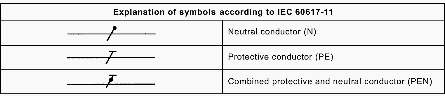
Symbols appearing in DC distribution schemes //
TT system
A polarity of the system and the exposed conductive-parts are connected to two electrically independent earthing arrangements (Figure 1). If necessary, the middle point of the supply can be connected to earth (Figure 2).


Go back to DC Earthing Arrangements ↑
TN system
Polarity or the middle point of the supply, is directly earthed. The exposed conductive parts are connected to the same earthed point. Three types of TN system are defined according to whether the earthed polarity and the protective conductor are separated or not:
- TN-S DC distribution system
In which throughout the system, a separate protective conductor is used - TN-C-S DC distribution system
In which neutral and protective functions are combined in a single conductor in a part of the system - TN-C DC distribution system
In which neutral and protective functions are combined in a single conductor throughout the system
Go back to DC Earthing Arrangements ↑
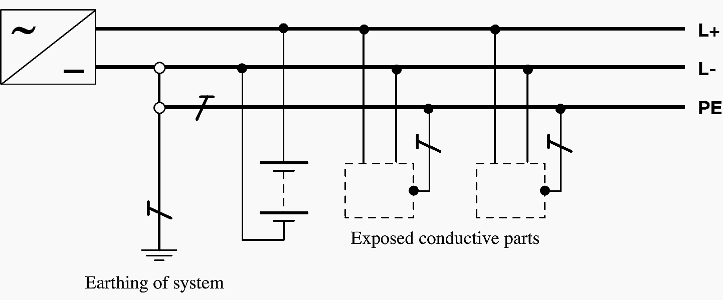
a. TN-S system
The earthed line conductor (for example L–) in system (Figure 3) or the earthed mid-wire conductor, M, in system (Figure 4) are separated from the protective conductor throughout the system.

Go back to DC Earthing Arrangements ↑
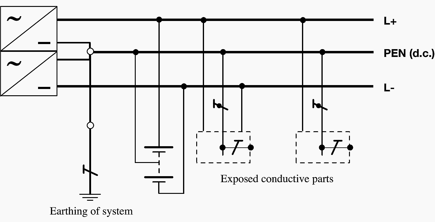
b. TN-C system
The functions of the earthed line conductor (for example L–) in system (Figure 5) and protective conductor are combined in one single conductor called PEN (d.c.) throughout the system, or the earthed mid-wire conductor, M, in system (Figure 6) and protective conductor are combined in one single conductor PEN (d.c.) throughout the system.

Go back to DC Earthing Arrangements ↑
c. TN-C-S system
The functions of the earthed line conductor (for example L–) in system (Figure 7) and protective conductor are combined in one single conductor PEN (d.c.) in parts of the system, or the earthed mid-wire conductor, M, in system (Figure 8) and protective conductor are combined in one single conductor called PEN (d.c.) in parts of the system.


Go back to DC Earthing Arrangements ↑
IT system
The supply source is not earthed. The exposed-conductive-parts are connected to the same earthing point.


Go back to DC Earthing Arrangements ↑
Protection against direct and indirect contact
To the purpose of protection against direct and indirect contacts, the Standard IEC 60364-4 prescribes that the protective device shall automatically disconnect the supply, so that in the event of a fault between a live part and an exposed-conductive-part or a protective conductor, a voltage exceeding 120 V (DC) does not persist for a time sufficient to cause harmful physiological effects for a human body.
For IT systems, the automatic opening of the circuit is not necessarily required in the presence of a first fault!
For particular environments tripping times and voltage values lower than the above mentioned ones may be required.
Further requirements for DC systems are being studied at present.
The measures of protection against direct contact are:
- Insulation of live parts with an insulating material which can only be removed by destruction (e.g. cable insulation).
- Barriers or enclosures: live parts shall be inside enclosures or behind barriers providing at least the degree of protection IPXXB or IP2X. For horizontal surfaces the degree of protection shall be of at least IPXXD or IP4X.
- Obstacles: the interposition of an obstacle between the live parts and the operator prevents unintentional contacts only, but not an intentional contact by the removal of the obstacle without particular tools.
- Placing out of reach: simultaneously accessible parts at different potentials shall not be within arm’s reach.
Go back to DC Earthing Arrangements ↑
References //
- Technical Application Paper Circuit-breakers for direct current applications by ABB
- IEC standard 60364-1 – Electrical installations of buildings – Part 1: Fundamental principles, assessment of general characteristics, definitions


One point is not clear: What determines whether to earh/ground the positive or negative terminal in dc power supply system?
You should connect your armour on both sides to a proper ground also because of EMC reasons.
Dear Ejaz
I suggest you ground the cable to both sides of the line with the DC line.
Dear advard,
I need some suggestions from you. We are using single1.8 kv armoured (awa) cable for DC system in solar plant and maximum voltage we get from one string is 1000 v DC. Our cable are armoured but armoured are not grounded, can you tell me it is necessary to ground and any standards which shows that armoured should be grounded.
Most household loads are DC or can be made DC. Solar PV panels generate DC power which has to be stored in DC batteries or converted to hydrogen by DC electrolysis so it makes sense to have a DC distribution system, .