
Estimated Study Time: 17 minutes
DOL Motor Starter Principles & Wiring
Different starting methods are employed for starting induction motors because Induction Motor draws more starting current during starting. We use a variety of starters in order to protect the windings from being damaged by the high current flow that is occurring during the motor starting process. When it comes to motor starters, the Direct On Line starter is the most straightforward choice for the induction motor.

The Direct On Line Motor Starter (DOL) consist a MCCB or Circuit Breaker, Contactor and an overload relay for protection.
Electromagnetic contactor which can be opened by the thermal overload relay under fault conditions. Typically, the contactor will be controlled by separate start and stop buttons, and an auxiliary contact on the contactor is used, across the start button, as a hold in contact. I.e. the contactor is electrically latched closed while the motor is operating.
Let’s start discussion with the principle of a DOL motor starter.
Principle of Direct On Line Starter (DOL)
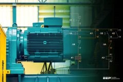
To start, the contactor is closed, applying full line voltage to the motor windings. The motor will draw a very high inrush current for a very short time, the magnetic field in the iron, and then the current will be limited to the Locked Rotor Current of the motor. The motor will develop Locked Rotor Torque and begin to accelerate towards full speed.
As the motor accelerates, the current will begin to drop, but will not drop significantly until the motor is at a high speed, typically about 85% of synchronous speed. The actual starting current curve is a function of the motor design, and the terminal voltage, and is totally independent of the motor load.
Provided the torque developed by the motor exceeds the load torque at all speeds during the start cycle, the motor will reach full speed. If the torque delivered by the motor is less than the torque of the load at any speed during the start cycle, the motor will stops accelerating.
If the starting torque with a DOL starter is insufficient for the load, the motor must be replaced with a motor which can develop a higher starting torque.
Figure 1 – Direct on-line motor starting scheme
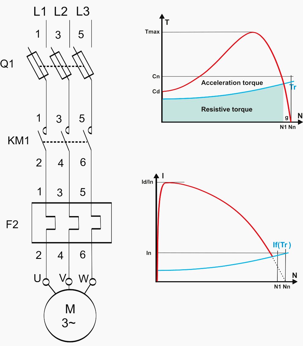
The acceleration torque is the torque developed by the motor minus the load torque, and will change as the motor accelerates due to the motor speed torque curve and the load speed torque curve. The start time is dependent on the acceleration torque and the load inertia.
Note that the DOL starting have a maximum start current and maximum start torque.
This may cause an electrical problem with the supply, or it may cause a mechanical problem with the driven load. So this will be inconvenient for the users of the supply line, always experience a voltage drop when starting a motor. But if this motor is not a high power one it does not affect much.
Parts of DOL Starters
Contactors and Coil
Magnetic contactors are electromagnetically operated switches that provide a safe and convenient means for connecting and interrupting branch circuits. Magnetic motor controllers use electromagnetic energy for closing switches. The electromagnet consists of a coil of wire placed on an iron core.
When a current flow through the coil, the iron of the magnet becomes magnetized, attracting an iron bar called the armature.
Figure 2 – Magnetic contactor coil, main / power contacts and auxiliary contacts
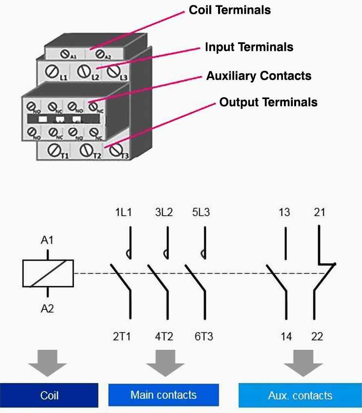
An interruption of the current flow through the coil of wire causes the armature to drop out due to the presence of an air gap in the magnetic circuit.
Line-voltage magnetic motor starters are electromechanical devices that provide a safe, convenient, and economical means of starting and stopping motors, and have the advantage of being controlled remotely. The great bulk of motor controllers sold are of this type.
A contact is conducting metal parts which completes or interrupt an electrical circuit.
- NO – normally open contact
- NC – normally closed contact
Suggested Reading – Mastering schematic drawings: Analyzing seal-in contacts in motor control circuits
Mastering schematic drawings: Analyzing seal-in contacts in motor control circuits
Over Load Relay (Overload protection)
Overload protection for an electric motor is necessary to prevent burnout and to ensure maximum operating life.
Under any condition of overload, a motor draws excessive current that causes overheating. Since motor winding insulation deteriorates due to overheating, there are established limits on motor operating temperatures to protect a motor from overheating. Overload relays are employed on a motor control to limit the amount of current drawn.
The ideal and easiest way for overload protection for a motor is an element with current-sensing properties very similar to the heating curve of the motor which would act to open the motor circuit when full-load current is exceeded. The operation of the protective device should be such that the motor is allowed to carry harmless over-loads but is quickly removed from the line when an overload has persisted too long.
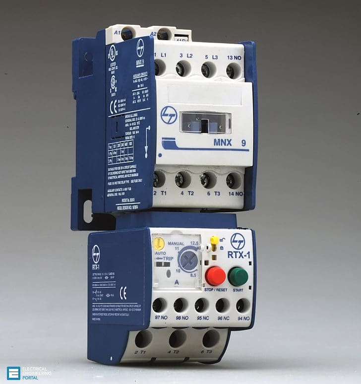
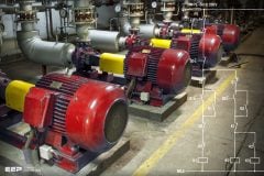
Figure 3 – Thermal (Overload) Motor Relay Protection (on photo: RTX relay with MNX contactor)
Normally fuses are not designed to provide overload protection. Fuse is protecting against short circuits (over current protection). Motors draw a high inrush current when starting and conventional fuses have no way of distinguishing between this temporary and harmless inrush current and a damaging overload. Selection of Fuse is depend on motor full-load current, would “blow” every time the motor is started.
On the other hand, if a fuse were chosen large enough to pass the starting or inrush current, it would not protect the motor against small, harmful overloads that might occur later.
The overload relay is the heart of motor protection. It has inverse-trip-time characteristics, permitting it to hold in during the accelerating period (when inrush current is drawn), yet providing protection on small overloads above the full-load current when the motor is running. Overload relays are renewable and can withstand repeated trip and reset cycles without need of replacement.
Overload relays cannot, however, take the place of over current protection equipment.
Figure 4 – Motor thermal overload relay
The overload relay consists of a current-sensing unit connected in the line to the motor, plus a mechanism, actuated by the sensing unit, which serves, directly or indirectly, to break the circuit.
Overload relays can be classified as being thermal, magnetic, or electronic:
- Thermal Relay: As the name implies, thermal overload relays rely on the rising temperatures caused by the overload current to trip the overload mechanism. Thermal overload relays can be further subdivided into two types: melting alloy and bimetallic.
- Magnetic Relay: Magnetic overload relays react only to current excesses and are not affected by temperature.
- Electronic Relay: Electronic or solid-state overload relays, provide the combination of high-speed trip, adjustability, and ease of installation. They can be ideal in many precise applications.
Wiring of DOL Starter
1. Main Contact
- Contactor is connecting among Supply Voltage, Relay Coil and Thermal Overload Relay.
- L1 of Contactor Connect (NO) to R Phase through MCCB.
- L2 of Contactor Connect (NO) to Y Phase through MCCB.
- L3 of Contactor Connect (NO) to B Phase through MCCB.
NO Contact (-||-):
- (13-14 or 53-54) is a normally Open NO contact (closes when the relay energizes)
- Contactor Point 53 is connecting to Start Button Point (94) and 54 Point of Contactor is connected to Common wire of Start/Stop Button.
NC Contact (-|/|-):
- (95-96) is a normally closed NC contact (opens when the thermal overloads trip if associated with the overload block)
2. Relay Coil Connection
- A1 of Relay Coil is connecting to any one Supply Phase and A2 is connecting to Thermal over Load Relay’s NC Connection (95).
3. Thermal Overload Relay Connection:
- T1,T2,T3 are connect to Thermal Overload Relay
- Overload Relay is Connecting between Main Contactor and Motor
- NC Connection (95-96) of Thermal Overload Relay is connecting to Stop Button and Common Connection of Start/Stop Button.
Wiring Diagram of DOL Starter

Working principle of DOL Starter
The main heart of DOL starter is Relay Coil. Normally it gets one phase constant from incoming supply Voltage (A1). When Coil gets second Phase relay coil energizes and Magnet of Contactor produce electromagnetic field and due to this Plunger of Contactor will move and Main Contactor of starter will closed and Auxiliary will change its position NO become NC and NC become (shown Red Line in Diagram) .
Pushing Start Button
When We Push the start Button Relay Coil will get second phase from Supply Phase-Main contactor (5) – Auxiliary Contact (53) – Start button-Stop button-96-95-To Relay Coil (A2). Now Coil energizes and Magnetic field produce by Magnet and Plunger of Contactor move.
Main Contactor closes and Motor gets supply at the same time Auxiliary contact become (53-54) from NO to NC .
Release Start Button
Relay coil gets supply even though we release Start button. When We release Start Push Button Relay Coil gets Supply phase from Main contactor (5) -Auxiliary contactor (53) – Auxiliary contactor (54) -Stop Button-96-95-Relay coil (shown Red / Blue Lines in Diagram).
In a motor Overload Condition the motor will be stopped by intermission of Control circuit at Point 96-95.
Pushing Stop Button
When we push Stop Button Control circuit of Starter will be break at stop button and Supply of Relay coil is broken, Plunger moves and close contact of Main Contactor becomes Open, Supply of Motor is disconnected.

Motor Starting Characteristics on DOL Starter
- Available starting current: 100%.
- Peak starting current: 6 to 8 Full Load Current.
- Peak starting torque: 100%
Advantages of DOL Starter
- Most Economical and Cheapest Starter
- Simple to establish, operate and maintain
- Simple Control Circuitry
- Easy to understand and trouble‐shoot.
- It provides 100% torque at the time of starting.
- Only one set of cable is required from starter to motor.
- Motor is connected in delta at motor terminals.
Disadvantages of DOL Starter
- It does not reduce the starting current of the motor.
- High Starting Current: Very High Starting Current (Typically 6 to 8 times the FLC of the motor).
- Mechanically Harsh: Thermal Stress on the motor, thereby reducing its life.
- Voltage Dip: There is a big voltage dip in the electrical installation because of high in-rush current affecting other customers connected to the same lines and therefore not suitable for higher size squirrel cage motors
- High starting Torque: Unnecessary high starting torque, even when not required by the load, thereby increased mechanical stress on the mechanical systems such as rotor shaft, bearings, gearbox, coupling, chain drive, connected equipments, etc. leading to premature failure and plant downtimes.
Features of DOL starting
- For low- and medium-power three-phase motors
- Three connection lines (circuit layout: star or delta)
- High starting torque
- Very high mechanical load
- High current peaks
- Voltage dips
- Simple switching devices
Direct On Line Motor Starter (DOL) is suitable for:
- A direct on line starter can be used if the high inrush current of the motor does not cause excessive voltage drop in the supply circuit. The maximum size of a motor allowed on a direct on line starter may be limited by the supply utility for this reason. For example, a utility may require rural customers to use reduced-voltage starters for motors larger than 10 kW.
- DOL starting is sometimes used to start small water pumps, compressors, fans and conveyor belts.
Direct On Line Motor Starter (DOL) is NOT suitable for:
- The peak starting current would result in a serious voltage drop on the supply system
- The equipment being driven cannot tolerate the effects of very high peak torque loadings
- The safety or comfort of those using the equipment may be compromised by sudden starting as, for example, with escalators and lifts.
Suggested Course – Motor Control Schematics Course For True Engineers
Related electrical guides & articles


Jignesh Parmar
Electrical Middle management professional having more than 22 years rich and dynamic experience in Project Execution / Project Management / Designing / Maintenance diversifies from Electrical Power Transmission (400KV/220KV/66KV)- Distribution(11KV/220V) to Lifts-HVAC-Ventilation-Fire Fighting-Fire Alarm-Lifts-CCTV-Stack Parking Works (High Rise Buildings, Townships, Shopping Complex, Commercial Complex, School, Temple).Profile: Jignesh Parmar

Hi,
Normally we use following formula to to calculate the DOL Cable sizing calculations :
DOL
Following formula will be used for calculating voltage available at the motor terminals during Steady state.
Vm = (VN + jo) – 3 x Ifl (Cos – j sin ) (R +jX)
Following formula will be used for calculating voltage available at the motor terminals during starting.
Vm = (VN + jo) – 3 x LRC (Cos – j sin ) (R +jX)
Que : Can you please let me know, from which IS / IEC / IEEE this derived and or if nay formula is there, please let me know which is the same with relevant standard number n clause number.
Thanks
Mahamuni
7977969164
I have a single phase machine which I want to connect to 3 phase DOL Starter how can I connect them?
Short the Y n B phase and connect pHASE to R and short circuited Y n B to Neutral
i really want to learn more about mor controls.
its good
Can you please tell me when the overload relay need to be used and when motor starter protector (mpcb) need to be used while selecting motor starter?
OLR means Over load relay. Mostly it contain a thermal bimetallic strip. (This will sense the cable temperature and inrush currently)
The root cause is high inrush current. Effect is increase in cable temp. OLR will trip based on the ratting. It wont allow you to reset untill the problem subside.
But MPCB will sense only the inrush current. If it is designed neck to neck. then for DOL it will cause often trip issue due to sudden inrush current at the starting.
But the same MPCB might work fine with Start to delta starter.
i have seen a motor with 2 contactors instead of 1 contactors.
the motor connection follows as 3P source, 3pole circuit breaker, 3 pole contactor(1) with coil supply sourced from OLR contactor (2) OLR , and 3 pole contactor(2) with coil supply from the PLC command. can you pls explain this configuration , what are the advantages of it
My friend have 3 kw induction motor and he connect motor to supply only by MCB and the motor winding is damaged and he buy other new motor. And i want to install protection by DOL to motor rpm 2820 what can i do ?
Its very good lesson and iget the important hint as i electrician and work on water pump from 5kw upto 12okw
its good guidance for an electrician to build up his ability to install every electrical machines
Direct online starter is my project topic please can I get the full work well package please
I have a 9.5hp single phase 240 volt fan motor wired directly through a 60 amp circuit breaker, There are no leads from the motor for thermal overload protection. Am I good with just the circuit breaker?
For sizing of the generator do we need to consider starting current when the motor will be started or no.
Yes
Hello EEP.
Thanks for the article, it’s awesome.
Here my question, Why do we call the DOL as a starting method of a motor?
Basically, the starting method’s aim is to limit/reduce the starting current and its effect on the supply system.
However, the DOL is not contributing anything in limiting the starting current or supporting the supply system.
What’s your opinion on my view of understanding particularly the DOL starting of a motor?
Respected Sir,
I want one electrical device that is when we want start the T.V. and watching and if power fail T.V. will be off and again power has come I don’t want start the T.V. until we start the TV again manually. i.e. just like very small motor stator up to 5 AMP if any device or circuit board with fitting is available please inform me Sir.
Sir. this is my humble request only.
A.K.Patil.
KLE College of ENgg & Tech,
At & Post: Chikodi-591201
Dist: Belgaum (Karnataka State)
Phone :9449016366
I dosn’t recomand DOL system in this process.
I WANT TO KNOW MORE ABOUT THE FAULTS DONE BY THE NOISY RUNNING OF MOTOR AND OVERHEATING OF MOTOR WHEN A LOAD LIGHT IS APPLIED.
Combination DOL starter, NEMA Size 3, 480V, 3P, 60Hz, Draw-out type complete with Bucket, stubs, indicating lights (LED), handle and all the required accessories.
For 30 kW motors
please suggest me any model for this capicity in schnider , square D, siemens or ABB /GE as i am unable to find it out i laso need 2 in 11kw and one for 7.5 KW motor
thanks sir
I need information about dol starter
I bought one DOL STARTER yesterday for my 5HP machine. But, I have one doubt. Can i use this starter continuously for more than 18 hours or non- stopped. I’m expecting your reply ASAP.
THANK YOU.
Please tell me the Power rating of different type starter??
For 30Kw induction motor connected with Dol starter what will be staring current and till how many sec or min it will remain?
Hi Jignesh.. Its nice article…. i need to discuss more on the technical…. can you please share your contact number
Ravikumar Talawar
I am an electrical contractor I am sufferlng a lots of trouble from a 220V D.O.L L&T starter. When I want to stop the motor by pushing red stop button, then the motor should have to stop but It is not happening. How can it solved? Ple
Hi, the best is using frequency inverter. It have decelerate time setting to stop the motor.
Knowledgeable portal…….. ???????
Hello,
I am facing problem of Operation of DOL starter, 3 Phase, 3 HP Motor through PLC.
I have 24VDC Coil, 5 Amp resistive load on 8 QTY connected to my PLC card, This is smoke extraction system and there are five zone with five different PLC installed, each zone has Eight 3HP fans working in Primary and secondary configuration. When the PLC program starts based on Fire Signal 4qty of FANS starts, but I am getting a 110VAC P-P Surge on my 24 VDC power which is killing my PLC output card. Our Observation is that there is some problem in the starter panel, because of which the surge is getting transferred from Our relay Contact to Coil. The Contact are connected directly in the control circuit of DOL to switch on KM1 contactor. can you please explain this phenomenon or the reasoning of this problem.
I believe your PLC card is getting damaged by the reverse voltage surge when the contactor coil is turned off. The contactor (or relay) coil is a rather large inductor and when the drive current from your 24VDC PLC is opened, the coil (inductor) tries to keep the current flowing by creating a large (100’s of volts) voltage spike.
The solution is to use a diode across the DC coils in a reverse direction (diode cathode goes to PLC output card source, Anode to -). Many contactors have a snubber option which plugs in and does this function. Research this.
AC coils have a similar need but cant use a diode so they use another device as a snubber which is either a dual direction diode (TVS), an MOV, or a simple RC ( 47 Ω + 0.1 uF typ) — as with most things there is a reason for which device to use and the RC values so do your research.
Good luck
really helpful ??
it’s very nice explanation
Very smartly and knowledgeably explained. We expect better engineering in life
Sir,D.O.L stater kitne HP tak ke induction motors me use kiye jate hai
Upto 10HP
upto 15 kw
I am an electrical contractor and have a problem with an elevator soft start always dimming out the voltage at an apartment bldg. We have upgraded the xfmr and the wire from the utility but still have the brown out. Can you help me with the calcs and explaining the delta in the wye starter? thanks!
i having 2 hp motorpump by using dol starter.in starter again and again relay was damaged the realy setting value is 2.7 its range is 2.5-4.0the motor we are using for chemical water draining. i checked continuity to L-L,L-body its ok but when i started the motor in fraction of seconds the relay fused out what the reason i cant find it please tell me and suggestion me.
Is an overload relay designed to take longer to trip for high inrush currents in a motor and to take a shorter time to trip for lower overload currents? Thank you!
Well I just wanna know that what is the approximate starting time of motor if it is using DOL starter/ soft starter.
Very good.
I WANT ONE DEVICE URGENTLY.MY CONTACT NO. IS 09966778080.ACTUALLY I AM SEE IN NEWS PAPER THIS IS FREE FOR AP AGRICULTURE LABOURS.
i want to know disadvantages of DOL method
starter motor,direct on line pump,90kw,150A,550v with circuit breaker 250MA earth leakage relay start/stop push button.
Kindly give a quote on above
very well
D.A.E. Electrical & simple B.A. & Three years electric filed experience
Sir You are good, explanation was clear
It is very useful for me . This artical is very much suitable for industrial application as well as educational application .
good it is a good site we can ever have in the world
Basic information about dol starter
Dear sir
I was suffering from my 3 point starter. I have 5 HP motor it is connected by 3 phase startor . it is used to ground water lifting. Start the motor, trip the starter ofter half on hour, then countnusly trip the starter. Please tell me how to phase my problem.
Dear YVN
pl change the contact of starter as it sparking and becoming hot. pl try and report.
I wish to know what is the KW diff between a motor connected with DOL starter & again connected with VFD drive assuming 1005 speed setting.
I want to connect a centurion g switch to my dol starter le1 d 253 is it possible and a diagram would be appreciated thanks
information is helpful to the leaner
could you kindly help us with calculations about Dol starter and even symbols of main componets
Would you also show how to calculate the DOL Starter rating calculations? That would be helpful…
Here it is :)
https://electrical-engineering-portal.com/download-center/electrical-software/dol-star-delta-starter-components
Good day Sir
I am a student looking for that software for dol-start -delta for simulation
its work in delta only
The electrical circuits are very helpful to the learners at all levels.
The circuit diagrams are very educative and very understable
very help full
inshallah u get more success
The drawings are okay,well simplified
still explanatory answer with starting and running characetstics for steady load is expected.
why we use DOL starter for below 5HP motor?
Respected sir,
how select fuse for 3 phase motor
sir, please tell me about the sizing of overload relay(i.e. how to select overload relay for a motor of specific capacity).
Dear sir,
we are drilling machine manufacturer, I need help, we have fitted 3-Phase 1.5HP motor in machine controlled with Reverse/Forward Switch, now we wish to add Emergency Push Button Stop, where should I give connection for it? what other components we require for it? (someone suggested me pushbuttton with NC connector- but the NC has only 2 Nodes as 3-phase must have 3 nodes in it) kindly help me,
Thanks in advance.
Just connect a mushroom-type industrial grade emergency stop button in series with the stop push in the control circuit of the motor. Please consult a certified technician / engineer for its proper installation and adherance to all safety norms.
I guess the esteemed author of this page will also support my suggestion :)
Yes the drawing is understandable………………….Well done
can a push button control three phase starter , work properly even if there is no main fuse and please send me functions all the components of DOL starter
Hi, my question is which starter recommended to be used with compressor? DOL or Star-Delta?
i think it s better to go for star-delta for rating higher than 10hp?
How can I use three phase to run single phase motor. thanks
Dol starters used for star connected motors or delta connected motors???
my Q is , when overload relay is open condition then i put in yellow LED to indicate its overload causes this open condition but how to yellow LED glow when its open condition????
can i use asingle phase motor acontorctor?
i would like to connect a 7.5hp motor to dol starter.what will happen
Dear sir
you can use DOL Starter for operate 7.5 Hp Motor.
I am no expert but usually for motor rating above 5 HP we use star delta starter.
One reason being higher the rating more is the starting inrush current.
Nice articles, Thanks
In case of 120V Single-Phase DOL Motor control 1)How neutral should be wired -Should it be wired through overload relay or not.
2) Live phase -can it be wired through one contact of contactor and overload relay or it should be routed through all three contacts or any two contacts.
How cn I download it??
Download what? Technical article?
Usually this is set to full load current for a DOL motor starter, and root 3 of the full load current for a star-delta starter. Dependent on the equipment being protected, electronic overload relays are available which can offer a better accuracy/reliability than the bimetallic strip with an thermal overload relay
Hello . Good day I am a bit confused about the DOL and Delta starter. Can anyone please help me to differentiate the difference? What is the basic formula for DOL, 3P? there was a question ,What size genset is needed to start a 3 phase electric motor Direct on Line (DOL) start? using 85HP ? can anyone give me the step by step answer? thank you
85hp=85*746=63410watt=63.48kw You have need minimum 80 KVA Genset..85 hp motor is may be star delta starter use.
What should be the setting on thermal overload device for a given running current of motor ie what percentage of running current.
thanks