
Why directional overcurrent protection?
Why do we use directional overcurrent protection? When does fault current direction become important? Well, electrical power grid comprises a network of power stations, substations and transmission lines. As well as the simple single-end-fed radial system, there are other more complex systems such as double-end-fed power systems and parallel feeders in ring formation.
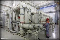
 The essentials of directional overcurrent protection in electrical power grid (on photo: ABB REF615 protection relay; credit: MARUF KHAN via Youtube)
In many cases, it is therefore not only necessary to know the magnitude of the fault current, but also its direction.
A double-end-fed radial system is shown in Figure 1. In this example, the line is fed from both ends. The protection zones are indicated by ellipses. The requirement is to open all breakers in any one protection zone where the fault occurs, but none of the others.
In this example, it is impossible to set up an adequate protection scheme using non-directional protection devices.
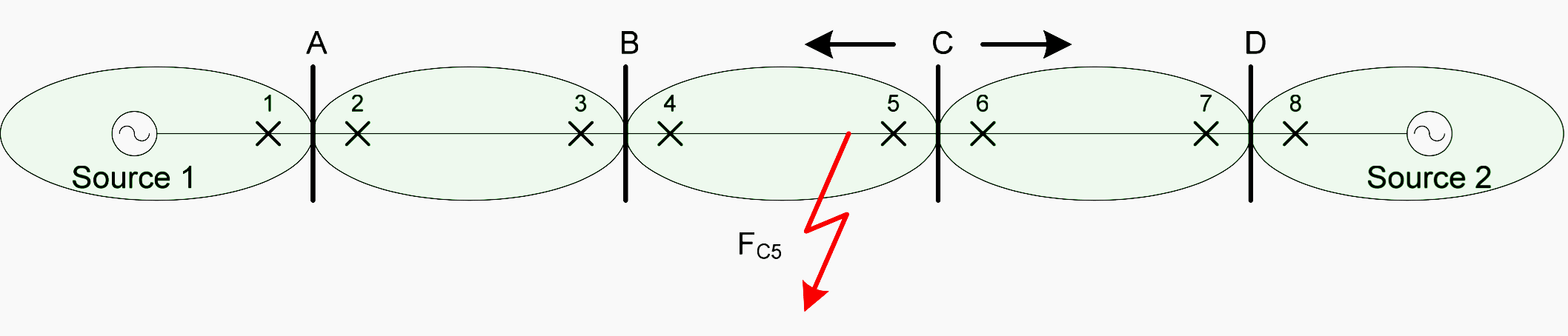
Consider a fault FC5. As defined by the zones, only CBs 4 and 5 should trip. As CB 3 is in close proximity to CB 4, there would be no great difference in fault current flowing through these two circuit breakers, therefore IDMT IEDs (Inverse Definite Minimum Time protection relay) would not be able to discriminate between them. The same situation applies for CB 5 and CB 6.
Directional overcurrent protection devices can achieve this requirement, albeit at extra cost. Directional IEDs determine the direction of the fault current by measuring the voltage with a voltage transformer as well as the current with a current transformer, and establishing the phase difference.
This technical article does not go into details of exactly how this is achieved, but it can be seen that it is possible to determine the direction of the fault current and base a tripping decision on this criterion.
Consider again a fault at FC5. This time let us assume we have directional IEDs. If we configure the IEDs to trip for overcurrents only if the direction of the current flow is away from the bus, CB 4 and CB 5 will trip, but CB 3 and CB 6 will not.
To summarize //
The overcurrent IED should trip whenever the fault power flows away from the bus, but should restrain whenever the fault power flows towards the bus. There are other situations, which do not involve dual sources, where directional protection devices are necessary.
Parallel feeders in single-end-fed system
One example is for a single-end fed system of parallel feeders. Figure 2 shows a situation where a fault on one of the parallel lines is fed from both the faulted line and the healthy one too.
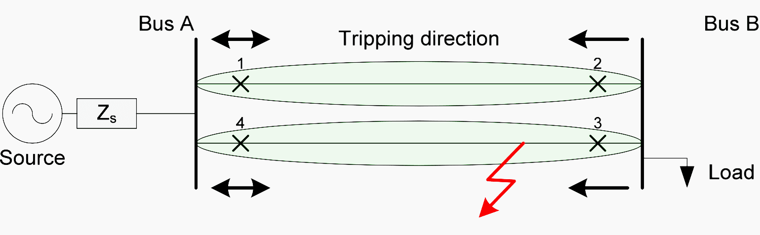
This diagrams shows that a fault current will not only flow from the source, through CB 4, but also from the source, through CB 1, CB 2, Bus B and CB3. If non-directional IEDs are used, all circuit breakers will trip, thus isolating the healthy section of line between (1) and (2).
Directional IEDs are more expensive than non- directional ones. What is more, they necessitate the use of an additional voltage transformer. For these reasons, they should only be used when absolutely necessary. You can see by inspection that in this example, non-directional IEDs will suffice for positions (1) and (4).
Ring main feeder system
Another example where directional IEDs are called for is in a ring main feeder system, as depicted in Figure 3. Such a system allows supply to be maintained to all loads in spite of a fault on any section of the feeder. A fault in any section causes only the CBs associated with that section to trip.
Power then flows to the load through the alternative path.
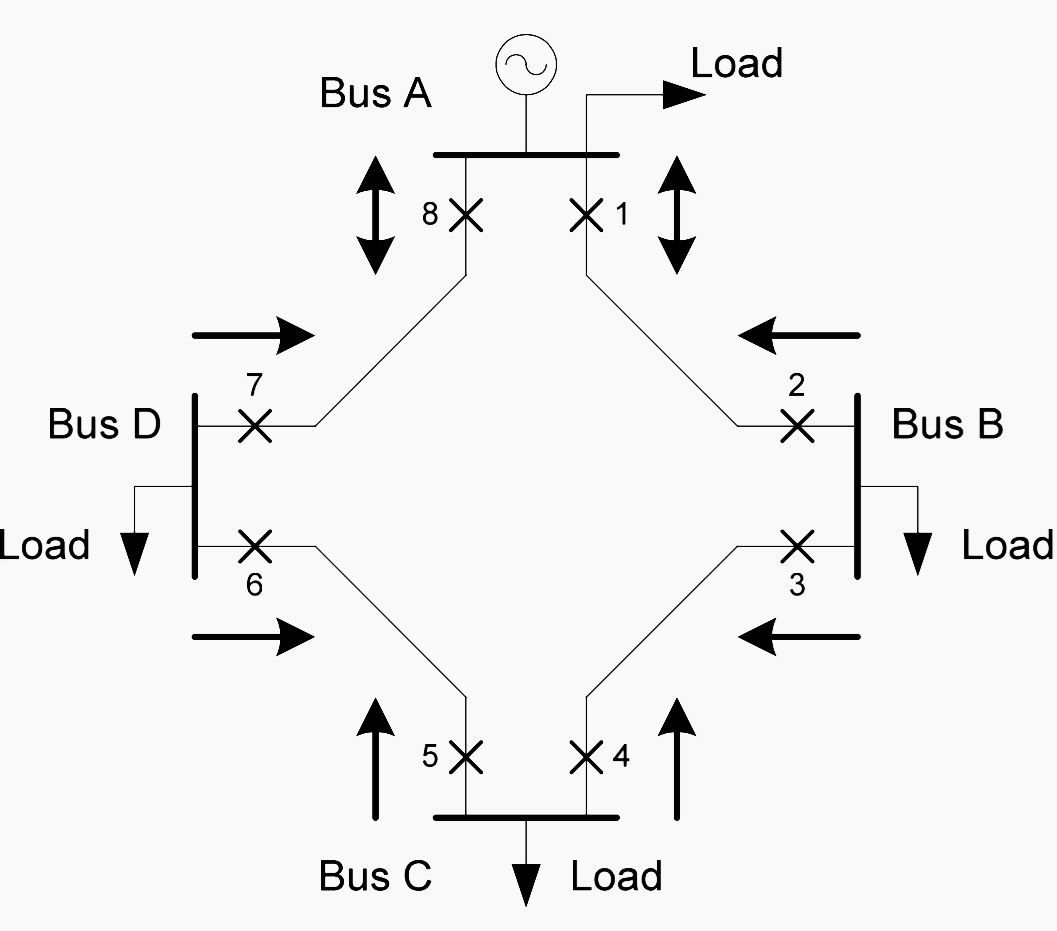
The directional IEDs and their tripping direction are indicated by arrows in the diagram. The double- ended arrows indicate non-directional IEDs, as these will trip with currents flowing in either direction.
Directional overcurrent protection (VIDEO)
Reference // Substation Automation Principles by Michael J Bergstrom


Can you help me with an article regarding setting values of I2 protection on electrical Motors?
The protection Relay is tripping many times when the system has voltage fluctuations.
Best Regards,
Fisnik
Hi, I would like to see a typical design of substation with two 2000kva transformers 13.8kv/600v with separate primary feeding two busbars connected with tie switch (NO). Each bus is feeding 3000hp booster pump. What the best controls to protect the transformer (primary and secondary), secondary bus bars and the motors.
Thanks
Adnan Alsaadi (P.Eng.)