Distance relay impedance
Some numerical relays measure the absolute fault impedance and then determine whether operation is required according to impedance boundaries defined on the R/X diagram. Traditional distance relays and numerical relays that emulate the impedance elements of traditional relays do not measure absolute impedance.

They compare the measured fault voltage with a replica voltage derived from the fault current and the zone impedance setting to determine whether the fault is within zone or out-of-zone. Distance relay impedance comparators or algorithms which emulate traditional comparators are classified according to their polar characteristics, the number of signal inputs they have, and the method by which signal comparisons are made.
The common types compare either the relative amplitude or phase of two input quantities to obtain operating characteristics that are either straight lines or circles when plotted on an R/X diagram.
Please note that this technical article is not about the basics of distance protection. But, just in case, let’s say a few introduction words:
The basic principle of distance protection involves the division of the voltage at the relaying point by the measured current. The apparent impedance so calculated is compared with the reach point impedance. If the measured impedance is less than the reach point impedance, it is assumed that a fault exists on the line between the relay and the reach point.
At each stage of distance relay design evolution, the development of impedance operating characteristic shapes and sophistication has been governed by the technology available and the acceptable cost.
Since many traditional relays are still in service and since some numerical relays emulate the techniques of the traditional relays, a brief review of impedance comparators is justified.
- Amplitude and phase comparison
- Plain impedance characteristic
- Self-polarised Mho relay
- Offset Mho/Lenticular characteristics
- Fully Cross-Polarised Mho characteristic
- Partially Cross-Polarised Mho characteristic
- Quadrilateral characteristic
- Protection against power swings
1. Amplitude and Phase Comparison
Relay measuring elements whose functionality is based on the comparison of two independent quantities are essentially either amplitude or phase comparators. For the impedance elements of a distance relay, the quantities being compared are the voltage and current measured by the relay.
Any type of impedance characteristic obtainable with one comparator is also obtainable with the other. The addition and subtraction of the signals for one type of comparator produces the required signals to obtain a similar characteristic using the other type.
For example, comparing V and I in an amplitude comparator results in a circular impedance characteristic centred at the origin of the R/X diagram. If the sum and difference of V and I are applied to the phase comparator the result is a similar characteristic.
2. Plain Impedance Characteristic
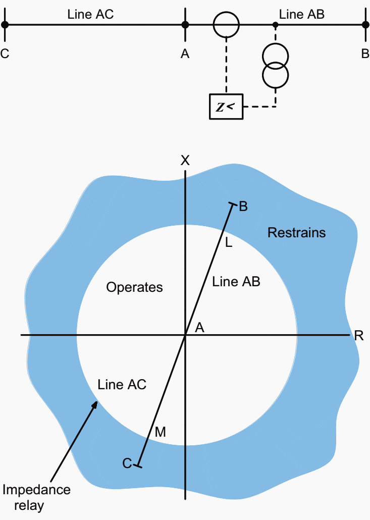
This characteristic takes no account of the phase angle between the current and the voltage applied to it. For this reason its impedance characteristic when plotted on an R/X diagram is a circle with its centre at the origin of the coordinates and of radius equal to its setting in ohms.
Operation occurs for all impedance values less than the setting, that is, for all points within the circle.
The relay characteristic, shown in Figure 1, is therefore non-directional, and in this form would operate for all faults along the vector AL and also for all faults behind the busbars up to an impedance AM. A is the relaying point and RAB is the angle by which the fault current lags the relay voltage for a fault on the line AB and RAC is the equivalent leading angle for a fault on line AC.
Vector AB represents the impedance in front of the relay between the relaying point A and the end of line AB. Vector AC represents the impedance of line AC behind the relaying point.
AL represents the reach of instantaneous Zone 1 protection, set to cover 80% to 85% of the protected line.

A relay using this characteristic has three important disadvantages:
- It is non-directional. It will see faults both in front of and behind the relaying point, and therefore requires a directional element to give it correct discrimination.
- It has non-uniform fault resistance coverage
- It is susceptible to power swings and heavy loading of a long line because of the large area covered by the impedance circle.
The impedance characteristic of a directional control element is a straight line on the R/X diagram, so the combined characteristic of the directional and impedance relays is the semi-circle APLQ shown in Figure 2.


If a fault occurs at F close to C on the parallel line CD, the directional unit RD at A will restrain due to current IF1. At the same time, the impedance unit is prevented from operating by the inhibiting output of unit RD. If this control is not provided, the under impedance element could operate prior to circuit breaker C opening.
Reversal of current through the relay from IF1 to IF2 when C opens could then result in incorrect tripping of the healthy line if the directional unit RD operates before the impedance unit resets.
In older relay designs, the type of problem to be addressed was commonly referred to as one of ‘contact race’.
3. Self-Polarised Mho Relay
The mho impedance element is generally known as such because its characteristic is a straight line on an admittance diagram.
It cleverly combines the discriminating qualities of both reach control and directional control, thereby eliminating the ‘contact race’ problems that may be encountered with separate reach and directional control elements.
This is achieved by the addition of a polarising signal.
The characteristic of a mho impedance element, when plotted on an R/X diagram, is a circle whose circumference passes through the origin, as illustrated in Figure 3 below.


This demonstrates that the impedance element is inherently directional and such that it will operate only for faults in the forward direction along line AB.
The self-polarised mho characteristic can be obtained using a phase comparator circuit which compares input signals S2 and S1 and operates whenever S2 lags S1 by between 90° and 270° as shown in the voltage diagram of Figure 3(a).
The two input signals are:
S2 = V-IZn
S1 = V
where:
- V = fault voltage from VT secondary
- I = fault current from CT secondary
- Zn = impedance setting of the zone
The characteristic of Figure 3(a) can be converted to the impedance plane of Figure 3(b) by dividing each voltage by I.
The impedance reach varies with fault angle. As the line to be protected is made up of resistance and inductance, its fault angle will be dependent upon the relative values of R and X at the system operating frequency.
Some users set the RCA less than the line angle, so that it is possible to accept a small amount of fault resistance without causing under-reach.
However, when setting the relay, the difference between the line angle θ and the relay characteristic angle Ø must be known. The resulting characteristic is shown in Figure 3 where GL corresponds to the length of the line to be protected.
With Ø set less than θ, the actual amount of line protected, AB, would be equal to the relay setting value AQ multiplied by cosine (θ−Ø).
Therefore the required relay setting AQ is given by:
AQ = AB / cos(θ−Ø)
Due to the physical nature of an arc, there is a non-linear relationship between arc voltage and arc current, which results in a non-linear resistance. Using the empirical formula derived by A.R. van C. Warrington, the approximate value of arc resistance can be assessed as:
Ra = L × 28,710 / I1.4
where:
- Ra = arc resistence (ohms)
- L = length of arc (metres)
- I = arc current (A)
On long overhead lines carried on steel towers with overhead earth wires the effect of arc resistance can usually be neglected. The effect is most significant on short overhead lines and with fault currents below 2000A (i.e. minimum plant condition), or if the protected line is of wood-pole construction without earth wires.
In the latter case, the earth fault resistance reduces the effective earth-fault reach of a ‘mho’ Zone 1 element to such an extent that the majority of faults are detected in Zone 2 time.
This problem can usually be overcome by using a relay with a cross-polarised mho or a polygonal characteristic.
It would therefore be taken into account only when assessing relay performance in terms of system impedance ratio.
4. Offset Mho / Lenticular Characteristics
Under close up fault conditions, when the relay voltage falls to zero or near-zero, a relay using a self-polarised mho characteristic or any other form of self-polarised directional impedance characteristic may fail to operate when it is required to do so.
If current bias is employed, the mho characteristic is shifted to embrace the origin, so that the measuring element can operate for close-up faults in both the forward and the reverse directions.
The offset mho relay has two main applications:
4.1 Third Zone and Busbar Back-Up Zone
In this application it is used in conjunction with mho measuring units as a fault detector and/or Zone 3 measuring unit. So, with the reverse reach arranged to extend into the busbar zone, as shown in Figure 4, it will provide back-up protection for busbar faults.


This facility can also be provided with quadrilateral characteristics. A further benefit of the Zone 3 application is for Switch-on-to-Fault (SOTF) protection, where the Zone 3 time delay would be bypassed for a short period immediately following line energization to allow rapid clearance of a fault anywhere along the protected line.
4.2 Carrier Starting Unit in Distance Schemes With Carrier Blocking
If the offset mho unit is used for starting carrier signaling, it is arranged as shown in Figure 4 above. The carrier is transmitted if the fault is external to the protected line but inside the reach of the offset mho relay, to prevent accelerated tripping of the second or third zone relay at the remote station.
Transmission is prevented for internal faults by operation of the local mho measuring units, which allows high-speed fault clearance by the local and remote end circuit breakers.
4.3 Application of Lenticular Characteristic
There is a danger that the offset mho relay shown in Figure 4 may operate under maximum load transfer conditions if Zone 3 of the relay has a large reach setting. A large Zone 3 reach may be required to provide remote back-up protection for faults on the adjacent feeder.
To avoid this, a shaped type of characteristic may be used, where the resistive coverage is restricted.
Figure 5 shows how the lenticular characteristic can tolerate much higher degrees of line loading than offset mho and plain impedance characteristics.
Reduction of load impedance from ZD3 to ZD1 will correspond to an equivalent increase in load current.


It can be observed in Figure 5 how the load area is defined according to a minimum impedance arc, constrained by straight lines which emanate from the origin, 0.
Modern numerical relays typically do not use lenticular characteristic shaping, but instead use load encroachment (load blinder) detection. This allows a full mho characteristic to be used, but with tripping prevented in the region of the impedance plane known to be frequented by load (ZA-ZB-ZC-ZD).
5. Fully Cross-Polarised Mho Characteristic
The previous section showed how the non-directional offset mho characteristic is inherently able to operate for close-up zero voltage faults, where there would be no polarising voltage to allow operation of a plain mho directional element.
One way of ensuring correct mho element response for zero-voltage faults is to add a percentage of voltage from the healthy phase(s) to the main polarising voltage as a substitute phase reference. This technique is called cross-polarising, and it has the advantage of preserving and indeed enhancing the directional properties of the mho characteristic.
By the use of a phase voltage memory system, that provides several cycles of pre-fault voltage reference during a fault, the cross-polarisation technique is also effective for close-up three-phase faults. For this type of fault, no healthy phase voltage reference is available.
Modern digital or numerical systems can offer a synchronous phase reference for variations in power system frequency before or even during a fault.
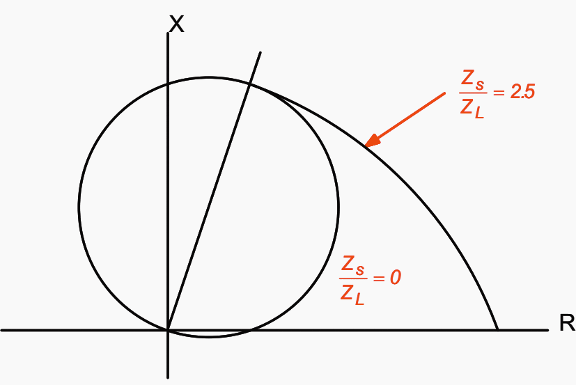
The amount of the resistive coverage offered by the mho circle is directly related to the forward reach setting. Hence, the resulting resistive coverage may be too small in relation to the expected values of fault resistance.
One additional benefit of applying cross-polarisation to a mho impedance element is that its resistive coverage will be enhanced.
This effect is illustrated in Figure 6, for the case where a mho element has 100% cross-polarisation. With cross-polarisation from the healthy phase(s) or from a memory system, the mho resistive expansion will occur during a balanced three-phase fault as well as for unbalanced faults.
The expansion will not occur under load conditions, when there is no phase shift between the measured voltage and the polarising voltage. The degree of resistive reach enhancement depends on the ratio of source impedance to relay reach (impedance) setting as can be deduced by reference to Figure 6.

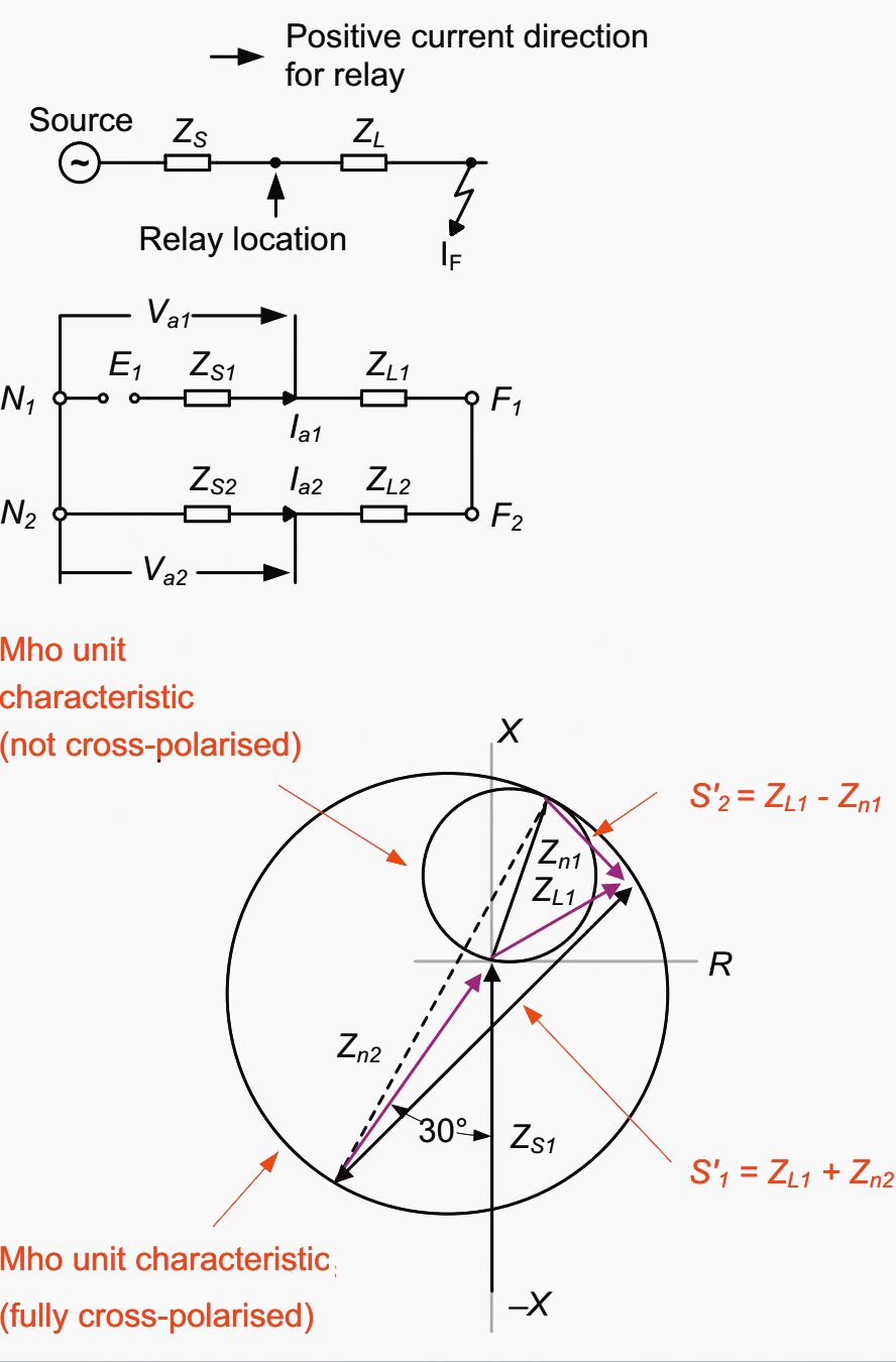
It must be emphasised that the apparent extension of a fully cross-polarised impedance characteristic into the negative reactance quadrants of Figure 7 does not imply that there would be operation for reverse faults.
With cross-polarisation, the relay characteristic expands to encompass the origin of the impedance diagram for forward faults only.
For reverse faults, the effect is to exclude the origin of the impedance diagram, thereby ensuring proper directional responses for close-up forward or reverse faults.

Fully cross-polarised characteristics have now largely been superseded, due to the tendency of comparators connected to healthy phases to operate under heavy fault conditions on another phase.
This is of no consequence in a switched distance relay, where a single comparator is connected to the correct fault loop impedance by starting units before measurement begins.
However, modern relays offer independent impedance measurement for each of the three earth-fault and three phase-fault loops. For these types of relay, mal-operation of healthy phases is undesirable, especially when single-pole tripping is required for single-phase faults.
6. Partially Cross-Polarised Mho Characteristic
Where a reliable, independent method of faulted phase selection is not provided, a modern non-switched distance relay may only employ a relatively small percentage of cross polarisation.
Figure 8 shows a typical characteristic that can be obtained using this technique (reference Micromho, Quadramho and Optimho family).


7. Quadrilateral Characteristic
This form of polygonal impedance characteristic is shown in Figure 9. The characteristic is provided with forward reach and resistive reach settings that are independently adjustable. It therefore provides better resistive coverage than any mho-type characteristic for short lines.
This is especially true for earth fault impedance measurement, where the arc resistances and fault resistance to earth contribute to the highest values of fault resistance.
To avoid excessive errors in the zone reach accuracy, it is common to impose a maximum resistive reach in terms of the zone impedance reach. Recommendations in this respect can usually be found in the appropriate relay manuals.


Quadrilateral elements with plain reactance reach lines can introduce reach error problems for resistive earth faults where the angle of total fault current differs from the angle of the current measured by the relay. This will be the case where the local and remote source voltage vectors are phase shifted with respect to each other due to pre-fault power flow.
This can be overcome by selecting an alternative to use of a phase current for polarisation of the reactance reach line.
A further factor is that the additional cost implications of implementing this characteristic using discrete component electromechanical or early static relay technology do not arise.
8. Protection against Power Swings – Use of the Ohm Characteristic
During severe power swing conditions from which a system is unlikely to recover, stability might only be regained if the swinging sources are separated.
Where such scenarios are identified, power swing, or out-of-step, tripping protection can be deployed, to strategically split a power system at a preferred location. Ideally, the split should be made so that the plant capacity and connected loads on either side of the split are matched.
This type of disturbance cannot normally be correctly identified by an ordinary distance protection.
Ohm impedance characteristics are applied along the forward and reverse resistance axes of the R/X diagram and their operating boundaries are set to be parallel to the protected line impedance vector, as shown in Figure 10.


The ohm impedance elements divide the R/X impedance diagram into three zones, A, B and C. As the impedance changes during a power swing, the point representing the impedance moves along the swing locus, entering the three zones in turn and causing the ohm units to operate in sequence.
Only an unstable power swing condition can cause the impedance vector to move successively through the three zones.
Therefore, other types of system disturbance, such as power system fault conditions, will not result in relay element operation.
Distance Module tutorial – OMICRON (VIDEO)
Source // Network Protection & Automation Guide by GE (Alstom Grid)






Thank you so much for these information 👍🙏
Best regards from Perú 🇵🇪
Tanks for these information, I would like to continue to interactive electrical power systems issues.
Love the site, need to get signed up to get to the rest of info
I very much enjoy getting the articles from this site — provides very nice summary information. Keep up the good work!!