
Estimated Study Time: 17 minutes
Function of Earthing
The electrical earthing system is designed to provide safe and correct operation of the network under normal, earth fault, and transient conditions. During earth fault conditions, large fault currents may flow via the general mass of the earth en route to the neutral point of the source transformer.
 Distribution earthing systems in LV/MV networks (design instructions and precautions)
The impedance of any ‘earthed’ metalwork (transformer tanks, switchgear enclosures, earth grids, etc.) with respect to the ‘true’ or ‘reference’ earth can lead to a rise in the potential that, if unmanaged, may pose a significant hazard to substation staff and/or the general public.
Low impedance earth is also required to effectively shunt transient overvoltages (caused by lightning discharges, switching surges, or other system disturbances) safely to earth. These overvoltages may cause extensive damage to equipment including ancillary items such as communications cables. Equipment damage might include insulation breakdown, thermal or mechanical damage and may result in electrically ignited explosions.
The rise in the potential of the earthing system under earth fault or transient conditions with respect to a remote reference point (assumed far enough away to be at ‘true earth’ or zero potential) is commonly referred to as Earth Potential Rise (EPR).
Typically, the electrode and its contact resistance are negligible and the resistance of earthing system will depend primarily on the resistivity of the soil in the area.
- Low-voltage Multiple Earthed Neutral (MEN) system
- Common Multiple Earthed Neutral (CMEN) System
- Separately Earthed System consisting of a Low Voltage Multiple Earthed Neutral (MEN) System and High Voltage Earth
- Accessible Metalwork
- Single Wire Earth Return (SWER) Earthing
- Transmission and Sub-transmission Earthing
1. Low Voltage Multiple Earthed Neutral (MEN) system
To achieve a low resistance between the neutral and ground, the low-voltage neutral in a MEN system should be earthed at the following locations:
- The LV neutral terminal of the transformer.
- The end of radials (main cables).
- Every 5th service pillar/pit or pole or every 250 “cable route meters”, whichever is the lesser distance.
- Switches (link pillars or disconnect links on poles).
Consequently, all metalwork of appliances, tools, etc. are also connected to the low voltage neutral. It is therefore essential that the neutral conductor be kept at, or close to earth potential.
2. The Common Multiple Earthed Neutral (CMEN) System
The Common Multiple Earthed Neutral System (CMEN system) is an extension of the MEN system whereby the low voltage neutral conductor (and hence the low voltage earthing system) is considered to be of low enough resistance to remote earth that the high voltage earthing system (transformers, zone substations, poles carrying exposed metalwork, etc. capable of being energized at high voltages) is allowed to be connected to it.
The CMEN system uses the low voltage neutral conductor as the return path for both low and high voltage fault currents. Very low resistance to earth for the neutral is required to ensure HV fault currents do not cause unacceptably high voltages on the LV network.
Within the conditions required for creating a CMEN system are:
- Less than 1Ω resistance between the network-neutral and earth (i.e. ‘connected’ resistance) AND
- A minimum of three transformers with LV neutral interconnected.
The large number of electrodes required for the formation of the CMEN system is based around AS2067:2016, Appendix B – distribution substations earthing system. There is also the additional general requirement that individual earth resistance (i.e. disconnected from the network-neutral) must be less than 30 Ω for pole-mounted plant and less than 10 Ω for the ground-mounted plant. The lower earthing resistance for the ground-mounted plant is because there is a greater chance of the equipment being touched.
Refer to Figure 1 showing earthing requirements for a typical CMEN earthing system at a pole.
Figure 1 – Typical CMEN earthing system (illustrated for overhead network)

In high load density areas, conditions generally allow a CMEN system. It is typically in lower load density, more sparsely populated areas where conditions for CMEN are not achievable and separately earthed HV and LV are required.
The CMEN system is sometimes referred to as a ‘bonded’ or ‘common’ earthing system as the high voltage and low voltage earthing systems are bonded together.
The advantages of using the CMEN system are:
- Only one earthing system need to be installed at distribution transformers
- Step and touch potential problems are reduced and
- Earth potential rise (EPR) problems associated with electrical plant in close proximity to telecommunications plant are also reduced.
- Earth fault currents are higher, so upstream protection can clear the fault quicker.
The CMEN system is the preferred method by which to earth distribution network, however, should only be employed in areas where there is an abundance of low-voltage interconnections and low overall resistance to ground is achievable.
3. Separately Earthed System consisting of a Low Voltage Multiple Earthed Neutral (MEN) System and High Voltage Earth
In cases where the conditions required for CMEN earthing set out in Section 2 cannot be met, the high voltage earth must be kept separate from the LV MEN system. Typically this would occur in rural areas with low load density.
Separation is required to ensure high voltage earth faults, lightning impulses, or switching surges (e.g. conducted to earth through surge arresters) do not cause excessive EPR on the LV system.
The high voltage earthing system provides an earth return path for plant and equipment capable of being energized by the high voltage system (e.g. surge arresters, transformer tank).
The general requirement is that the HV individual earth resistance must be less than 30Ω for the pole-mounted plant and less than 10Ω for the ground-mounted plant. The lower earthing resistance for the ground-mounted plant is because there is a greater chance of the equipment being touched.
Figure 2 – Typical separate earthing system for overhead network

To ensure that the potential rise during high voltage faults does not cause a safety hazard to the operator or the general public, the high voltage earth is always insulated and separated from the low voltage earth in a separately earthed system, as shown in Figures 2 and 3.
Figure 3 – Typical separate earthing system for an underground network

Important Note:
The 5-meter minimum clearance zone is measured from the edge of the plinth, a clearance zone to be maintained free from metallic objects, buildings, and structures, including foundations. The clearance zone should be a road reserve or an easement to prevent encroachment and turfed or landscaped if necessary with mulched beds and shrubs.
In a Separate Earthing System, the high voltage earth should always be insulated and separated from the low voltage MEN system.
4. Accessible Metalwork
The general requirement is to ensure that any accessible metalwork (i.e. conductive surface able to be touched by persons) does not become energized at a hazardous voltage.
Accessible metalwork includes:
- Operating handles for air break switches and cable guards on poles
- Equipment cabinets.
For situations with CMEN, the general requirement is that accessible metalwork should be bonded to the CMEN. For separately earthed situations on an overhead network, the accessible metalwork on poles should not be bonded to the HV earth (but should be bonded to the LV earth/neutral if present).
For separately earthed equipment cabinets on an underground network, the frame should be bonded to the HV earth and the earth mat/grading ring.
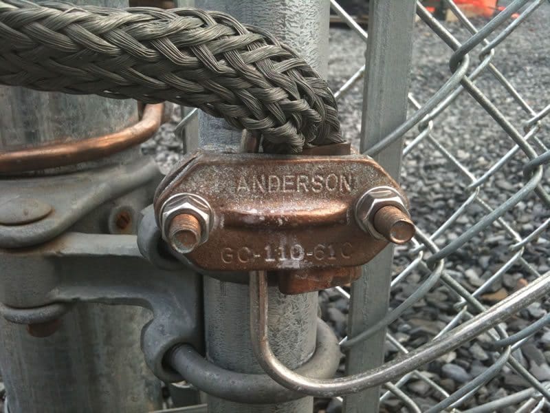
Figure 4 – Substation fence earthing
5. Single Wire Earth Return (SWER) Earthing
The Single Wire Earth Return system requires separate and distinct high voltage and low voltage earthing systems. SWER systems consist of a single isolating transformer (typically 100 – 150kV.A, 5 – 8A), and a number of individual SWER distribution transformers.
The isolating transformer carries all the load of the SWER scheme connected to it. The primary winding of the isolating transformer is connected between two phases of the conventional 11kV (or 33kV) system. The secondary winding has one terminal forming the high voltage (Single Wire) of the SWER line (typically 12.7kV) and the other is connected to the earth.
The individual distribution transformers have one terminal connected to the high voltage line, and the other to the earth. The earth acts as the return conductor back to the isolating transformer to complete the circuit (Earth Return). This is illustrated in Figure 5 below.

In normal three-phase systems, earthing of 11kV equipment is merely a protective measure, and current flows in the earth circuit only for the duration of a fault. However, in the case of a SWER system, the 12.7kV earthing installation carries the load current of the circuit as well as any fault current.
The safe operation of any electrical distribution system necessitates the maintenance of low resistance earths in order to ensure that protective devices will operate under fault conditions. Hence, within certain limits, the SWER system presents no greater problem than is encountered for the conventional system, assuming that no increase in resistance occurs owing to the passage of load current.
The resistance to the ground of the high voltage earthing system should not exceed the values shown in Figure 5.
The low voltage earthing system for the SWER system provides the earth return path for the low voltage and is separate from the high voltage earthing system. In general SWER systems will only have one customer at each transformer. Thus for each customer installation, there will only be a low voltage earth electrode system at the transformer and an earth electrode at the customer’s premises earthing the low voltage neutral.
Hence, the resistance to the ground of the low voltage earthing system at the transformer should not exceed 10 Ω.
The SWER system is a separately earthed system. The high voltage and low voltage earth cables should be insulated and there should be a minimum separation of 5m between the high voltage and low voltage earth electrodes.
6. Transmission and Sub-transmission Earthing
For sub-transmission (33kV) and transmission (110/132kV), it is important to ensure lightning impulses on overhead earthwires and any earth fault current, switching surges or lightning impulses from equipment do not cause excessive EPR on the LV system.
33kV OHEWs (overhead earthwires) are earthed with a maximum of 30 Ω resistance. LV cables should generally not be run on poles or structures with 110/132kV overhead circuits. Where this does occur, the LV earth electrodes should be separated from any 110/132kV earthing electrodes in the ground by a minimum of 20 m.
Suggested reading – Earthing system calculation for 132/11 kV, 1×40 MVA substation of steel factory
Earthing system calculation for 132/11 kV, 1×40 MVA substation of steel factory
Reference: Earthing guide by Energex
Related electrical guides & articles


Edvard Csanyi
Hi, I'm an electrical engineer, programmer and founder of EEP - Electrical Engineering Portal. I worked twelve years at Schneider Electric in the position of technical support for low- and medium-voltage projects and the design of busbar trunking systems.I'm highly specialized in the design of LV/MV switchgear and low-voltage, high-power busbar trunking (<6300A) in substations, commercial buildings and industry facilities. I'm also a professional in AutoCAD programming.
Profile: Edvard Csanyi

Very useful information regarding the subject matter
I like it
Keep up the good job!!!
Great work, it helps me to revise and keeps me updated on the technical knowledge.
Very informative topic.
Hello Mr. Edvard, I want to ask a question about grounding. If I have Transformers that grounded with a rod and the building was protected by Arrester and grounded too. Is there any regulation on how far the grounding transformer and grounding of Arrester?. Can we combine the transformer’s grounding and grounding of Arrester? Thanks…
I’m really grateful for this platform,
I have found that all the information I need to become an experienced Electrical Engineer in the community is right in here on EEP
I may not have enough funds on me right now, But
I’m looking forward to get myself a premium membership as soon as possible when I get it.
Thanks really much
usefull
The earthing systems for diffrent applications are described nicely.earthing plays an important role in protection of equipments and humanlife.Therefore effective earting and protection systems for electrical circuits in fundamental requirement.
What are some project topics on renewableenergy you have that you can sent for me?8
What are some project topics on Power Distribution you are working on? You can inform me soon as I am looking for most resent ideas on how I can start my thesis.
Want to write a thesis on renewable energy.Want topic on it.also want materials to enable me write a very good project.