
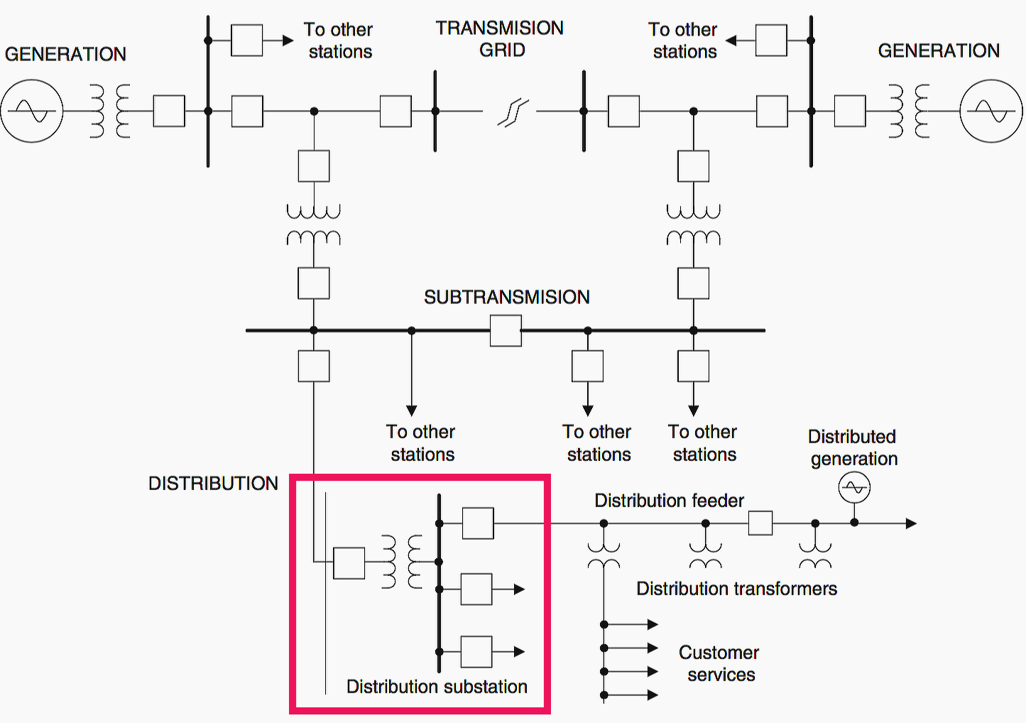
Distribution substation
Distribution substation typically operates at 2.4 – 34.5 kV voltage levels, and deliver electric energy directly to industrial and residential consumers. Distribution feeders transport power from the distribution substations to the end consumers’ premises. These feeders serve a large number of premises and usually contain many branches.
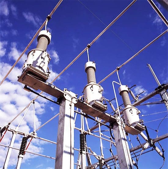
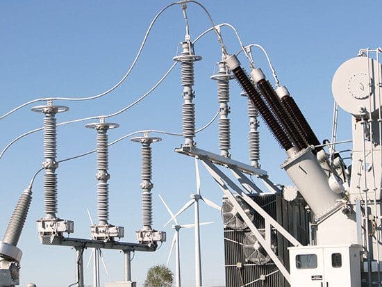
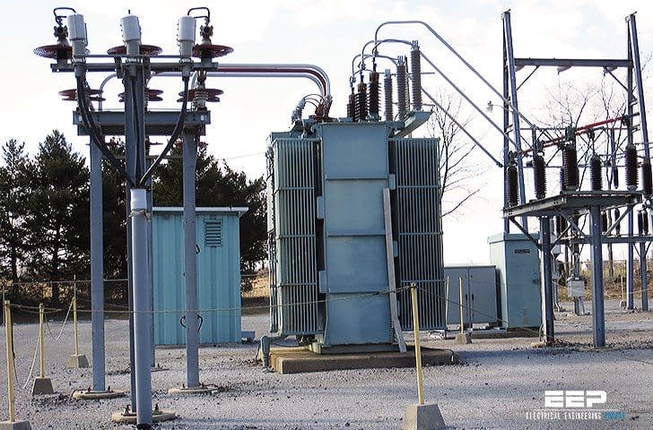 What is distribution substation and its main components? (on photo: 69kV substation in Stouchburg; credit: PA Powerliner via Flickr)
At the consumers’ premises, distribution transformers transform the distribution voltage to the service level voltage directly used in households and industrial plants, usually from 110 to 600 V.
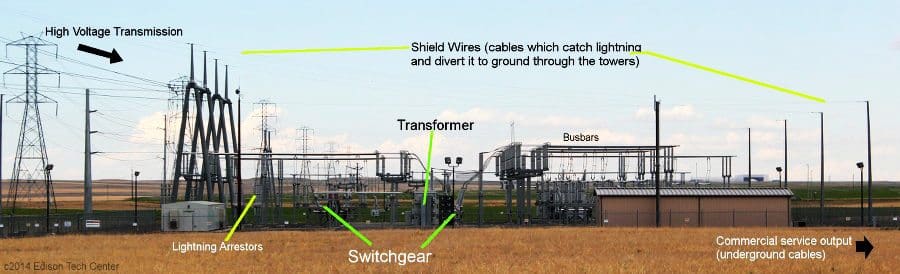
Distribution substation is generally comprised of the following major components:
- Supply Line
- Transformers
- Busbars
- Switchgear
- Outcoming feeders
- Switching apparatus
- Surge voltage protection
- Grounding
1. Supply Line
Distribution substation is connected to a sub-transmission system via at least one supply line, which is often called a primary feeder. However, it is typical for a distribution substation to be supplied by two or more supply lines to increase reliability of the power supply in case one supply line is disconnected.
Supply lines are connected to the substation via high voltage disconnecting switches in order to isolate lines from substation to perform maintenance or repair work.
Go back to Distribution Substation Components ↑
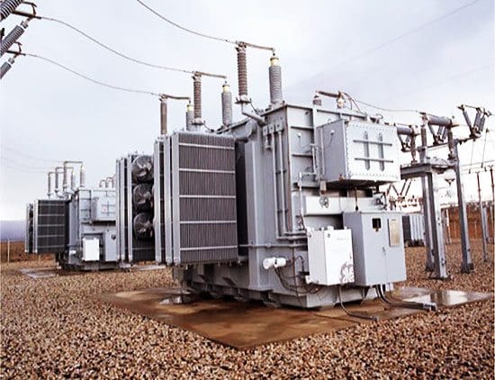
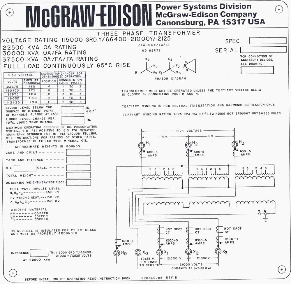
2. Transformers
Transformers “step down” supply line voltage to distribution level voltage. See Figure 3 below. Distribution substation usually employs three-phase transformers. However, banks of single-phase transformers can also be used.
For reliability and maintenance purposes, two transformers are typically employed at the substation, but the number can vary depending on the importance of the consumers fed from the substation and the distribution system design in general.
Transformers can be classified by the following factors:
a) Power rating
Which is expressed in kilovolt-amperes (kVA) or megavolts- amperes (MVA), and indicates the amount of power that can be transferred through the transformer. Distribution substation transformers are typically in the range of 3 kVA to 25 MVA.
b) Insulation
Which includes liquid or dry types of transformer insulation. Liquid insulation can be mineral oil, nonflammable or low-flammable liquids. The dry type includes the ventilated, cast coil, enclosed non-ventilated, and sealed gas- filled types.
Additionally, insulation can be a combination of the liquid, vapor, and gas-filled unit.
c) Voltage rating
Which is governed by the sub-transmission and distribution voltage levels substation to which the transformer is connected. Also, there are standard voltages nominal levels governed by applicable standards. Transformer voltage rating is indicated by the manufacturer.
Voltage rating dictates the construction and insulation requirements of the transformer to withstand rated voltage or higher voltages during system operation.
d) Cooling
Which is dictated by the transformer power rating and maximum allowable temperature rise at the expected peak demand. Transformer rating includes self-cooled rating at the specified temperature rise or forced-cooled rating of the transformer if so equipped.
Typical transformer rated winding temperature rise is 55°C/65°C at ambient temperature of 30°C for liquid-filled transformers to permit 100% loading or higher if temporarily needed for system operation.
Modern low-loss transformers allow even higher temperature rise. However, operating at higher temperatures may impact insulation and reduce transformer life.
e) Winding connections
Which indicates how the three phases of transformer windings are connected together at each side. There are two basic connections of transformer windings:
- Delta (where the end of each phase winding is connected to the beginning of the next phase forming a triangle); and
- Star (where the ends of each phase winding are connected together, forming a neutral point and the beginning of windings are connected outside).
Typically, distribution transformer is connected delta at the high-voltage side and wye at the low voltage side. Delta connection isolates the two systems with respect to some harmonics (especially third harmonic), which are not desirable in the system. A wye connection establishes a convenient neutral point for connection to the ground.
Learn all transformer vector groups ✔
f) Voltage regulation
Which indicates that the transformer is capable of changing the low voltage side voltage in order to maintain nominal voltage at customer service points. Voltage at customer service points can fluctuate as a result of either primary system voltage fluctuation or excessive voltage drop due to the high load current.
Transformer taps effectively change the transformation ratio and allow voltage regulation of 10–15% in steps of 1.75–2.5% per tap. Transformer tap changing can be manual or automatic.
However, only under-load type tap changers can operate automatically.
Go back to Distribution Substation Components ↑
3. Busbars
Busbars (also called buses) can be found throughout the entire power system, from generation to industrial plants to electrical distribution boards. Busbars are used to carry large current and to distribute current to multiple circuits within switchgear or equipment (Figure 5).
Plug-in devices with circuit breakers or fusible switches may be installed and wired without de-energizing the busbars if so specified by the manufacturer.
Originally, busbars consisted of uncovered copper conductors supported on insulators, such as porcelain, mounted within a non-ventilated steel housing. This type of construction was adequate for current ratings of 225–600 A.
As the use of busbars expanded and increased, loads demanded higher current ratings and housings were ventilated to provide better cooling at higher capacities.
By utilizing conduction, current densities are achieved for totally enclosed busbars that are comparable to those previously attained with ventilated busbars. Totally enclosed busbars have the same current rating regardless of mounting position. Bus configuration may be a stack of one busbar per phase (0–800 A), whereas higher ratings will use two (3,000 A) or three stacks (5,000 A).
Each stack may contain all three phases, neutral, and grounding conductors to minimize circuit reactance.
Busbars’ conductors and current-carrying parts can be either copper, aluminum, or copper alloy rated for the purpose.
Compared to copper, electrical grade aluminum has lower conductivity and lower mechanical strength.
Generally, for equal current-carrying ability, aluminum is lighter in weight and less costly. All contact locations on current-carrying parts are plated with tin or silver to prevent oxides or insulating film from building up on the surfaces.
Outdoor busbars are designed to operate reliably despite exposure to the weather. Available current ratings range from 600 to 5,000 A continuous current. Available short-circuit current ratings are 42,000–200,000 A, symmetrical root mean square (RMS).
Go back to Distribution Substation Components ↑
4. Switchgear
Switchgear (Figure 6) is a general term covering primary switching and interrupting devices together with its control and regulating equipment. Power switchgear includes breakers, disconnect switches, main bus conductors, interconnecting wiring, support structures with insulators, enclosures, and secondary devices for monitoring and control.
Switchgear can be of outdoor or indoor types, or a combination of both. Outdoor switchgear is typically used for voltages above 26 kV, whereas indoor switchgear is commonly for voltages below 26 kV.
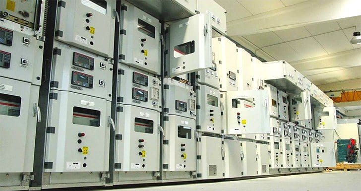
Indoor switchgear can be further classified into metal-enclosed switchgear and open switchgear, which is similar to outdoor switchgear but operates at lower voltages. Metal enclosed switchgear can be further classified into metal-clad switchgear, low voltage breaker switchgear, and interrupter switchgear.
Metal-clad switchgear can be characterized as follows:
- The primary voltage breakers and switches are mounted on a removable mechanism to allow for movement and proper alignment.
- Grounded metal barriers enclose major parts of the primary circuit, such as breakers or switches, buses, potential transformers, and control power transformers.
- All live parts are enclosed within grounded metal compartments. Primary circuit elements are not exposed even when the removable element is in the test, disconnected, or in the fully withdrawn position.
- Primary bus conductors and connections are covered with insulating material throughout by means of insulated barriers between phases and between phase and ground.
Go back to Distribution Substation Components ↑
5. Outcoming Feeders
A number of outcoming feeders are connected to the substation bus to carry power from the substation to points of service. Feeders can be run overhead along streets, or beneath streets, and carry power to distribution transformers at or near consumer premises.
The feeders’ breaker and isolator are part of the substation low voltage switchgear and are typically the metal-clad type.
When a fault occurs…
When a fault occurs on the feeder, the protection will detect it and open the breaker.
After detection, either automatically or manually, there may be one or more attempts to reenergize the feeder. If the fault is transient, the feeder will be reenergized and the breaker will remain closed. If the fault is permanent, the breaker will remain open and operating personnel will locate and isolate the faulted section of the feeder.
Go back to Distribution Substation Components ↑
6. Switching Apparatus
Switching apparatus is needed to connect or disconnect elements of the power system to or from other elements of the system. Switching apparatus includes switches, fuses, circuit breakers, and service protectors.
a) Switches
Switches are used for isolation, load interruption, and transferring service between different sources of supply.
Isolating switches are used to provide visible disconnect to enable safe access to the isolated equipment. These switches usually have no interrupting current rating, meaning that the circuit must be opened by other means (such as breakers). Interlocking is generally provided to prevent operation when the switch is carrying current.
Load-break switches are of the air- or fluid-immersed type. The interrupter switch is usually manually operated and has a “quick-make, quick-break” mechanism which functions independently of the speed-of-handle operation. These types of switches are typically used on voltages above 600 V.
For services of 600 V and below, safety circuit breakers and switches are commonly used. Safety switches are enclosed and may be fused or un-fused. This type of switch is operated by a handle outside the enclosure and is interlocked so that the enclosure cannot be opened unless the switch is open or the interlock defeater is operated.
Transfer switches can be operated automatically or manually.
Automatic transfer switches are of double-throw construction and are primarily used for emergency and standby power generation systems rated at 600 V and lower. These switches are used to provide protection against normal service failures.
Go back to Distribution Substation Components ↑
b) Fuses
Fuses are used as an overcurrent protective device with a circuit-opening fusible link that is heated and severed as overcurrent passes through it. Fuses are available in a wide range of voltage, current, and interrupting ratings, current-limiting types, and for indoor and outdoor applications.
Fuses perform the same function as circuit breakers, and there is no general rule for using one versus the other.
The decision to use a fuse or circuit breaker is usually based on the particular application, and factors such as the current interrupting requirement, coordination with adjacent protection devices, space requirements, capital and maintenance costs, automatic switching, etc.
Go back to Distribution Substation Components ↑
c) Circuit breakers
Circuit breakers are devices designed to open and close a circuit either automatically or manually. When applied within its rating, an automatic circuit breaker must be capable of opening a circuit automatically on a predetermined overload of current without damaging itself or adjacent elements. Circuit breakers are required to operate infrequently, although some classes of circuit breakers are suitable for more frequent operation.
The interrupting and momentary ratings of a circuit breaker must be equal to or greater than the available system short-circuit currents.
Circuit breakers are available for the entire system voltage range, and may be as furnished single-pole, double-pole, triple-pole, or four-pole, and arranged for indoor or outside use. Sulfur hexafluoride (SF6) gas-insulated circuit breakers are available for medium and high voltages, such as gas-insulated substations.
Different techniques are used to extinguish the arc, including:
- Lengthening the arc
- Intensive cooling (in jet chambers)
- Division into partial arcs
- Zero point quenching (contacts open at the zero current time crossing of the AC waveform, effectively breaking no-load current at the time of opening)
- Connecting capacitors in parallel with contacts in DC circuits
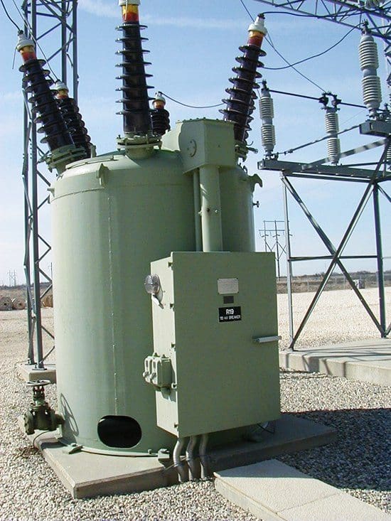
Traditionally, oil circuit breakers (Figure 7) were used in the power industry, which use oil as a media to extinguish the arc and rely upon vaporization of some of the oil to blast a jet of oil through the arc.
- Gas (usually sulfur hexafluoride) circuit breakers sometimes stretch the arc using a magnetic field, and then rely upon the dielectric strength of the sulfur hexafluoride to quench the stretched arc.
- Vacuum circuit breakers have minimal arcing (as there is nothing to ionize other than the contact material), so the arc quenches when it is stretched by a very small amount (<2–3 mm). Vacuum circuit breakers are frequently used in modern medium-voltage switchgear up to 35 kV.
- Air blast circuit breakers may use compressed air to blow out the arc, or alternatively, the contacts are rapidly swung into a small sealed chamber, where the escaping displaced air blows out the arc.
Indoor circuit breakers are rated to carry 1–3 kA current continuously, and interrupting 8–40 kA short-circuit current at rated voltage.
Go back to Distribution Substation Components ↑
7. Surge Voltage Protection
Transient overvoltages are due to natural and inherent characteristics of power systems. Overvoltages may be caused by lightning or by a sudden change of system conditions (such as switching operations, faults, load rejection, etc.), or both. Generally, the overvoltage types can be classified as lightning generated and as switching generated.
The magnitude of overvoltages can be above maximum permissible levels, and therefore needs to be reduced and protected against to avoid damage to equipment and undesirable system performance.
The occurrence of abnormal applied overvoltage stresses, either short term or sustained steady state, contributes to premature insulation failure. Large amounts of current may be driven through the faulted channel, producing large amounts of heat.
The appropriate application of surge-protective devices (Figure 8) will lessen the magnitude and duration of voltage surges seen by the protected equipment. The problem is complicated by the fact that insulation failure results from impressed overvoltages, and because of the aggregate duration of repeated instances of overvoltages.
Surge arresters have been used in power systems to protect insulation from overvoltages. Historically, the evolution of surge arrester material technology has produced various arrester designs, starting with the valve-type arrester, which has been used almost exclusively on power system protection for decades. The active element (i.e., valve element) in these arresters is a nonlinear resistor that exhibits relatively high resistance (megaohms) at system operating voltages, and a much lower resistance (ohms) at fast rate-of-rise surge voltages.
Arresters have a dual fundamental-frequency (RMS) voltage rating (i.e., duty- cycle voltage rating), and a corresponding maximum continuous operating voltage rating. Duty-cycle voltage is defined as the designated maximum permissible voltage between the terminals at which an arrester is designed to perform.
Go back to Distribution Substation Components ↑
8. Grounding
Grounding is divided into two categories: power system grounding and equipment grounding. Power system grounding means that at some location in the system there are intentional electric connections between the electric system phase conductors and ground (earth).
Power system grounding
System grounding is needed to control overvoltages and to provide a path for ground-current flow in order to facilitate sensitive ground-fault protection based on detection of ground-current flow.
Power system grounding can be as follows:
- Solidly grounded
- Ungrounded
- Resistance grounded
Each grounding arrangement has advantages and disadvantages, with choices driven by local and global standards and practices, and engineering judgment.
Solidly grounded systems are arranged such that circuit protective devices will detect a faulted circuit and isolate it from the system regardless of the type of fault. All transmission and most sub-transmission systems are solidly grounded for system stability purposes. Low voltage service levels of 120–480 V four-wire systems must also be solidly grounded for safety of life.
Where service continuity is required, such as for a continuously operating process, the resistance grounded power system can be used. With this type of grounding, the intention is that any contact between one phase conductor and a ground will not cause the phase overcurrent protective device to operate. Resistance grounding is typically used from 480 V to 15 kV for three-wire systems. Resistance grounding is achieved by connecting the neutral of the wye-connected winding of the power transformer to the ground through the resistor, or by employing special grounding transformers.
The operating advantage of an ungrounded system is the ability to continue operations during a single phase-to-ground fault, which, if sustained, will not result in an automatic trip of the circuit by protection!
Ungrounded systems are usually employed at the distribution level and are originated from delta-connected power transformers.
Equipment grounding
Equipment grounding refers to the system of electric conductors (grounding conductor and ground buses) by which all non-current-carrying metallic structures within an industrial plant are interconnected and grounded.
The main purposes of equipment grounding are:
- To maintain low potential difference between metallic structures or parts, minimizing the possibility of electric shocks to personnel in the area
- To contribute to adequate protective device performance of the electric system, and safety of personnel and equipment
- To avoid fires from volatile materials and the ignition of gases in combustible atmospheres by providing an effective electric conductor system for the flow of ground-fault currents and lightning and static discharges to eliminate arcing and other thermal distress in electrical equipment
It is bonded to the local supporting metal structure and to the switchgear so that the operator will not be exposed to a high differential voltage due to a fault in the substation.
Go back to Distribution Substation Components ↑
Reference // Distribution Systems, Substations, and Integration of Distributed Generation by John D. McDonald, Bartosz Wojszczyk, Byron Flynn, and Ilia Voloh


Good morning, great information, thank you
Great work..
Perfect platform
Very useful
Thanks a lot
Dear Sir,
Good night, it’s valuable post, thanks for sharing with us.
I wish your all success.
Best Regards,
Khandoker Md. Enamul Haq David
From Dhaka, Bangladesh.
How much power, in MW, can a distribution substation with a rating of 5MVA, safely handle? We plan to transmit the power of our 25MW hydro power plant using a 69kV line to the said substation. Thank you.
A very informative technical article. Thanks
The description here is very clear and easy to read and follow.
Well presented for someone who may not have an electrical background.
It is a good starting point for someone who is keen to know about electrical distribution.
Thank you
Anderw
I NEED BASIC DETAILS ABOUT ELECTRICAL
I’m PowerElectronics Engineer…Your Article are Always Informative and Interesting..Wish You All Of The Best..
I’d Like To Add Sth…i.e…If There Is a Possibility To Print In PDF Format For Free..
Thank You Very Much…
Quite informative, well-done Edvard.
Thank you Onuoma.
Very éducative article
Thank you Kimeng.
Merci pour votre effort et ces informations technique
Very informative article
Edvard, thanks for your frabjous technical articles. For dissemination of the tech information for the electrical engineering fraternity, pl.
You’re welcome Zaakaria!
Edvard, thanks for your frabjous technical articles. For dissemination of the tech information for the electrical engineering fraternity, pl. let me know, whether the articles can be shared on other forums??
You’re welcome Zaakaria, thank you very much! You can share the link of articles, but not complete articles.
thanks too much
thanks
Thank you very much for your courriels, i am very glad if you chow me the way to collect datas of say a certain small electrical network easily to be able to calculate the necessary unknowns; such as real power, reactive power, currents, voltages, the angle delta, the power factor, etc. thank you.
Thanks. How to control and how to regulate the voltage, the current, the power flowing from the distribution to the load. Is from the power station control?
Deep and simple overview, really appreciated. Congrats
Thank you Pietro.
Quite a good article. In Nigeria power distribution substations housing power transformers that are usually of 11 and 33 KV voltage levels and 2.5 to 15 MVA power ratings are called injection substations
complete and great article
Thumbs up
Excellent article. Just one correction(?) – section 2a says Distribution Transformers range from 3kVA-25MVA. Should that be 3MVA-25MVA?
In Nigeria, Distribution Transformer ranges from 50kVA to 900kVA or 1MVA but at injection substatio, we can have from 1MVA TO 25MVA step up power transformer
please, provide us pdf file about substation and distribution.
Edvard, thanks for your frabjous technical articles. For dissemination of the tech information for the electrical engineering fraternity, pl. let me know, whether the articles can be shared on other forums??
thanks