
Distribution transformers (50-2500 kVA)
The characteristic data of distribution transformers are determined by the requirements of the network. The effective power determined must be multiplied by the power factor cosφ to give the rated power SrT. In distribution networks the value uk= 6% is preferred.
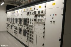
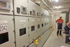
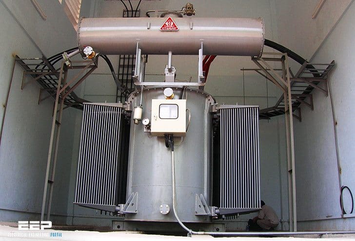 Selection of distribution transformers for supplying power to LV networks (photo credit: gelexcambodia.com)
Transformer losses are made up of no-load losses and short circuit losses. The no-load losses are caused by the continuous reversal of magnetization of the iron core and are practically constant and independent of loading. The short circuit losses are made up of the ohmic losses in the windings and losses due to leakage fields. They are proportional to the square of the loading.
In this technical article, the most important criteria for the selection of distribution transformers in the power range from 50 to 2500 kVA for supplying power to low voltage networks will be discussed.
- Requirement of operational safety:
- Routine tests (losses, uk, voltage test)
- Type testing (heating, surge voltage)
- Special tests (short circuit strength, noise)
- Electrical conditions:
- Short circuit voltage
- Connection symbol / vector group (learn more)
- Transformation ratio
- Installation conditions:
- Interior and outside installation
- Special local conditions
- Environmental protection conditions
- Designs: oil-filled or cast resin dry-type transformer
- Operating conditions:
- Loading capacity (oil-filled transformers or cast resin dry-type transformers)
- Load fluctuations
- Number of hours in operation
- Efliciency (oil-filled transformers or cast resin dry-type transformers)
- Voltage regulation
- Parallel transformer operation (learn more)
- Characteristic data for transformers with examples:
- Rated power SrT = 1000 kVA
- Rated voltage UrOS = 20 kV
- Lower side voltage UrUS = 0.4 kV
- Rated lightning impulse withstand voltage UrB = 125 kV
- Loss combination
- No-load losses P0 = 1700 W
- Short circuit losses Pk = 13000 W
- Acoustical power LWA = 73 dB
- Short circuit voltage ukr = 6%
- Transformation ratio PV/SV = 20 kV/0.4 kV
- Connection symbol Dyn5
- Termination systems, e.g. lower voltage and upper voltage side flange systems
- Interior or outside installation

Where:
- Cable conduit
- Zinc-plated flat steel grate
- Exhaust opening with protective grate
- Unscrewed conduit with pump
- Ramp
- Air intake opening with protective grave
- Gravel or crushed rock layer
- Ledge
The installation of transformers should be free of underground water and flooding. The cooling must be protected against sunlight. Fire protection measures and environmental compatibility must also be ensured. Figure 1 illustrates a transformer with oil filling < 1000 liters. Here, an impermeable floor is suflicient.
For oil filling > 1000 liters, oil collecting troughs or oil sumps are mandatory.
The size of the exhaust opening is shown without grate in Figure 2 for a room heating of 15 K.
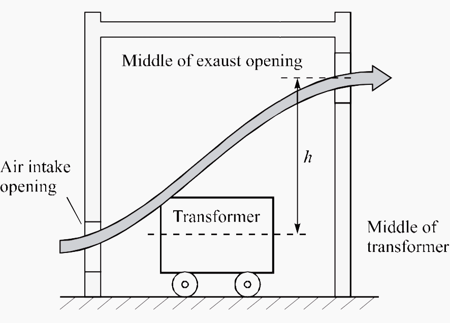
Pv = P0 + k × Pk75 [kW]
The meanings of the symbols are:
- A – Air exaust opening and intake opening
- Pv – Transformer power loss
- k = 1.06 for oil-filled transformers
- k = 1.2 for cast resin transformers
- Po – No-load losses
- Pk75 – Short circuit losses at 75° in kW
- h – Difference in height in meters
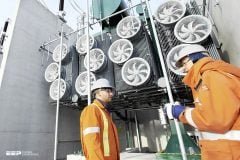
The heating losses which arise while operating a transformer (Figure 4) must be dissipated. If it is not possible owing to the conditions for installation to utilize natural ventilation, it is necessary to install a fan. The overall temperature of the transformer must not exceed 40°C.
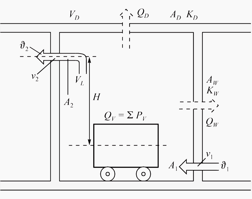
The overall losses in a transformer room are given by:
Qloss = ∑ Ploss
Ploss = P0 + 1.2 × Pk75 × (SAF / SAN)2
The total losses are dissipated through:
Qv = Qloss1 + Qloss2 + Qloss3
The individually dissipated amounts of heat can be calculated from the following:
Natural air current: Qloss1 = 0.098 × A1.2 × √HΔυL3
Losses dissipated by forced air currents (Figure 3):
Qloss3 = VL × CPL × ρ
Losses dissipated through walls and the ceiling (Figure 4):
Qloss2 = 0.7 × AW × KW × ΔυW + AD × KD × ΔυD
The meanings of the symbols are:
- Pv – Transformer power loss in kW
- Qv – Dissipated losses in kW
- QW,D – Dissipated losses through walls and ceiling in kW
- AW,D – Area ofwalls and ceiling in m2
- KW,D – Heat transfer coeflicient in kW/m2K
- SAF – Power for the cooling type AF in kVA
- SAN – Power for the cooling type AN in kVA
- VL – Air flow rate in m3/s, m3/h
- Qv1 – Part dissipated in natural air current in kW
- Qv2 – Part dissipated through walls and ceiling in kW
- Qv3 – Part dissipated in forced air current in kW
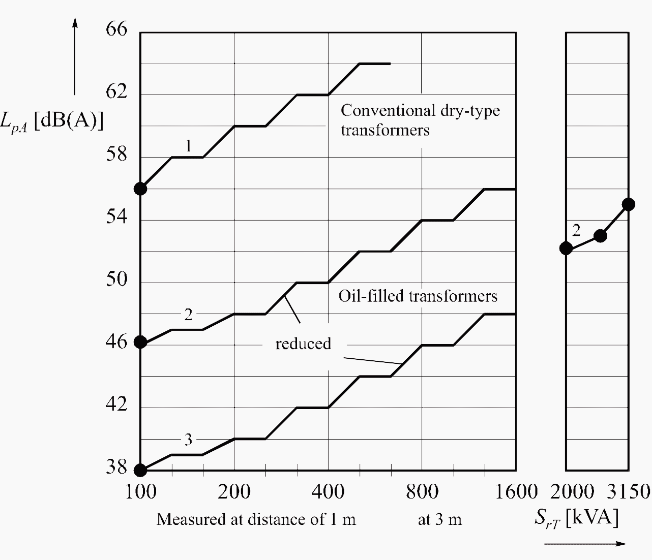
Figure 5 shows the noise level of different transformers according to IEC Publication 551. The magnetic noise is the result of oscillations of the iron core (induction-dependent) and depends on the material properties of the core laminations.
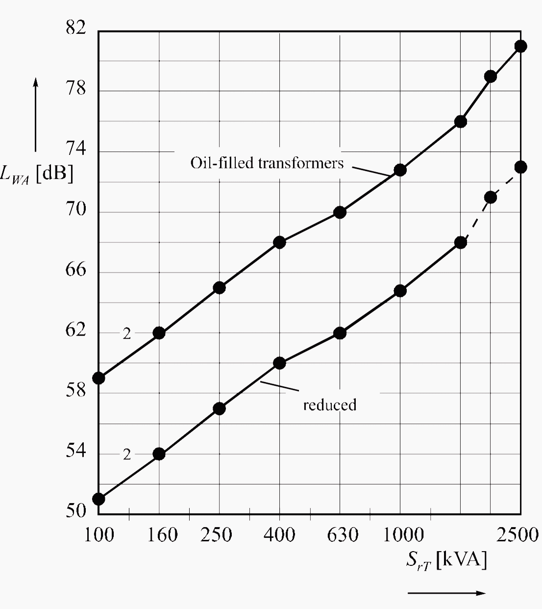
The acoustical power (Figure 6) is a measure of the noise level produced by an acoustical source.
50KVA distribution transformer 20Kv-400V
Reference // Analysis and design of low voltage power systems by Ismail Kasikci (Purchase hardcover from Amazon)


Edward, sorry to say there is a mistake in the second sentence of your article.
“The effective power determined must be multiplied by the power factor to give the rated power. ” has been mentioned where as fact of the matter is effective power is to be divided by power factor to give the rated power/apparent power etc.
Sharing valueable knowledge