


Estimated Study Time: 52 minutes
Twenty Most Impactful Trends
Go a year or less without learning a new technology, and you’re out of the game. The power engineering industry is definitely one of those fields where innovation happens fast. This article will go through the 20 defining trends in medium and high voltage systems, applications, and human competencies.
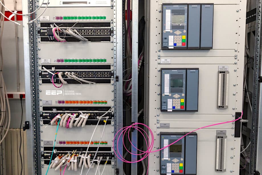 Don’t Become Obsolete: The Definitive Guide to What’s Next in Power Engineering
The global transition towards a decentralized, and digitalized energy grid represents one of the most profound engineering challenges of our time. This is not merely an incremental shift in how we generate power, but a complete reimagining of how energy is transmitted, distributed, controlled, and protected.
As we push towards aggressive climate targets and integrate vast amounts of variable renewable energy resources, the fundamental architecture of our medium voltage (MV) and high voltage (HV) networks is undergoing a radical transformation.
This transformation demands not only revolutionary hardware but also sophisticated new applications and, crucially, a new breed of power engineer equipped with interdisciplinary skills.
Historically, power engineering was dominated by heavy iron, massive copper conductors, mechanical switches, and steady, unidirectional power flow from large centralized synchronous generators to passive loads. Today, the grid is a highly dynamic, bidirectional, software-defined network.
It requires split-second decision-making, immense data processing capabilities, and components that can withstand unprecedented stress while minimizing environmental impact.
By examining these trends in detail, we can understand the interconnected nature of the modern grid and prepare for the challenges and opportunities that lie ahead.
Okay, let’s dive into the details!
- Part 1: New Equipment & Hardware Innovations
- Part 2: Advanced Applications & System Architectures
- Part 3: Emerging Human Skills & Interdisciplinary Competencies
- A Message to Young and Veteran Power Engineers
- Attachment (PDF) 🔗 A Guide to Substation Design, Operation, Technology Selection, and Asset Management
Part 1: New Equipment & Hardware Innovations
The physical components of the grid are evolving rapidly, driven by the need for higher efficiency, smaller footprints, advanced intelligence, and stricter environmental regulations.
These hardware innovations form the physical foundation of the smart grid.
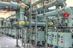
1. SF6-Free Switchgear
For decades, Sulfur Hexafluoride (SF6) has been the undisputed champion of electrical insulation and arc quenching in medium and high voltage switchgear. Its exceptional dielectric strength and thermal properties allowed engineers to design incredibly compact and reliable gas-insulated substations (GIS).
However, SF6 harbors a critical flaw: it is one of the most potent greenhouse gases known to humanity. Even minor leaks during operation, maintenance, or decommissioning pose a significant environmental hazard.
The first is the expanded use of vacuum interrupter technology, which has long dominated the medium voltage sector but is now being pushed into higher voltage classes.
Vacuum interrupters extinguish arcs effectively without any insulating gas, relying on the vacuum’s inherently high dielectric strength.
Figure 1 – SF6-free Blue GIS by Siemens Energy
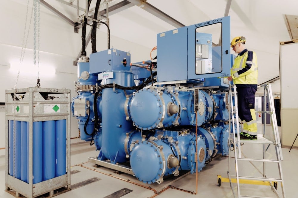
For applications where vacuum alone is insufficient or where compact dimensions are paramount, the industry is turning to alternative gas mixtures. These often involve clean air (a purified mixture of nitrogen and oxygen) or proprietary fluoronitrile-based gas mixtures, sometimes blended with CO2 or O2.
Furthermore, entirely new testing and certification protocols must be established to ensure that SF6-free equipment matches the reliability standards expected of critical infrastructure.
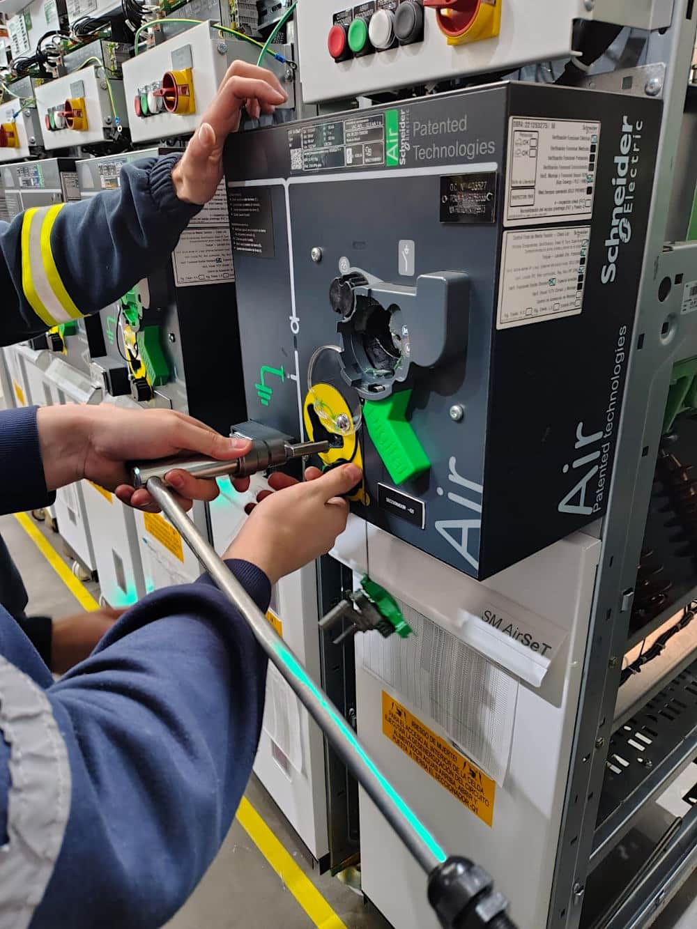
Figure 2 – SF6-Free Switchgear by Schneider Electric
2. Solid-State Transformers (SSTs)
The traditional iron-core and copper-coil transformer has been the workhorse of AC power systems since the late 19th century. While incredibly robust and highly efficient at basic voltage step-up and step-down operations, conventional transformers are inherently passive devices. They offer no dynamic control over voltage or power flow and are vulnerable to power quality issues like harmonics and voltage sags.
Enter the Solid-State Transformer (SST), a revolutionary application of high-frequency power electronics designed to replace or supplement traditional transformers, particularly at the medium voltage level.
Unlike a conventional transformer, an SST processes power through a series of power electronic conversion stages. Typically, this involves an AC-to-DC conversion (rectification), followed by a high frequency DC-to-AC conversion (inversion), a high-frequency isolation transformer (which is vastly smaller than a low-frequency 50/60Hz equivalent), and finally, another conversion stage back to the desired AC or DC output.
This complex architecture allows the SST to perform functions far beyond simple voltage transformation.
Furthermore, SSTs inherently provide both AC and DC connectivity, making them ideal hubs for modern microgrids that utilize DC for energy storage and EV charging.
While currently more expensive and complex than conventional transformers, ongoing advancements in power semiconductors are rapidly making SSTs
viable for critical grid applications.
Keep in mind that Solid State Transformers have not yet started to be used in MV and HV substations, but that the technology has been “conquered”, and that it is a matter of time (as well as money) before it becomes widely used.
Figure 3 – Solid-State Transformer (SST)
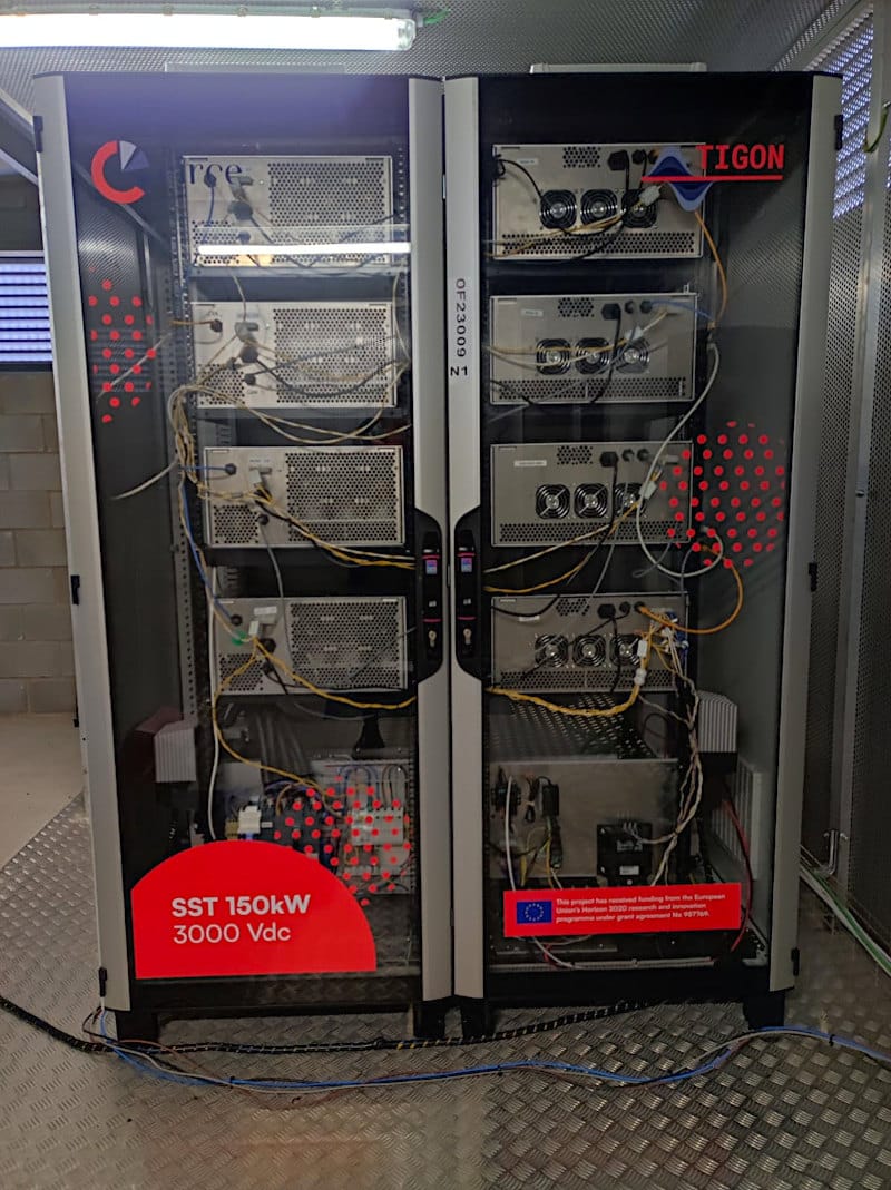
Figure 3 displays a solid-state transformer (SST) and its protection cabinet at the CEDER-CIEMAT facilities. This equipment is designed to convert a low-voltage AC network into a 3 kV DC network.
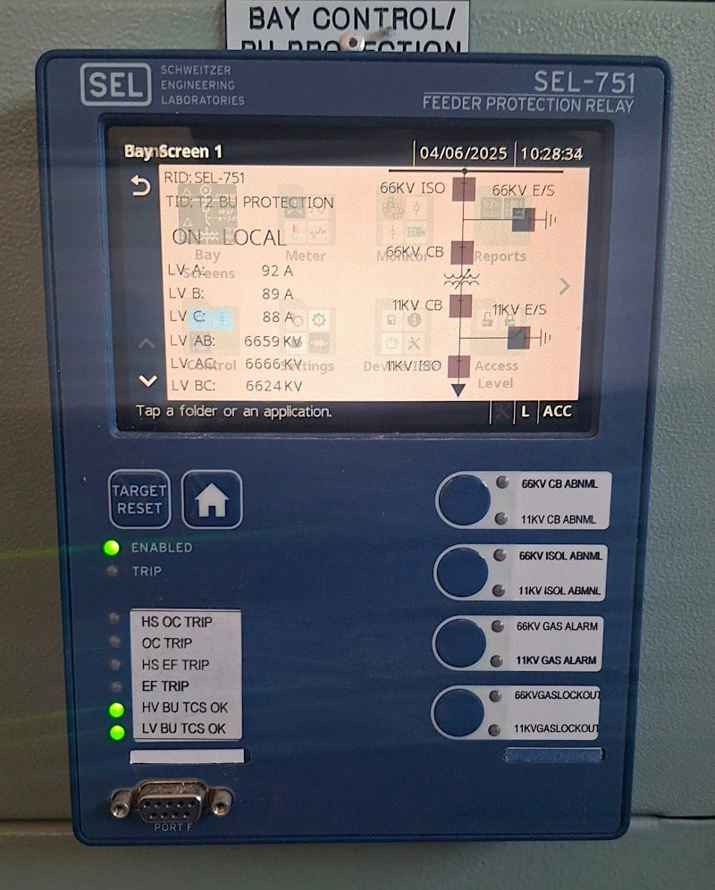
3. Advanced Intelligent Electronic Devices (IEDs)
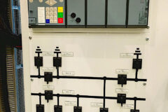
An advanced IED is no longer just a protection relay; it is a powerful embedded computer, often running specialized real-time operating systems, capable of performing a multitude of complex tasks simultaneously.
Modern IEDs process sampled values (digitized streams of current and voltage data) at incredibly high sampling rates directly from the primary equipment via process bus networks (such as IEC 61850). This high-fidelity data allows for the implementation of far more sophisticated protection algorithms, improving sensitivity, selectivity, and speed of operation.
They can detect high-impedance faults that would have eluded older relays and adapt their protection settings dynamically based on the current grid topology or operating conditions.
Furthermore, they are the primary interfaces for SCADA systems, providing real-time operational data, alarms, and sequence-of-events reporting.
The engineering challenge has shifted from hardware design to complex firmware development (often involving rigorous C/C++ programming) and intricate configuration logic to ensure these powerful devices perform flawlessly under extreme conditions.
Figure 4 – Example of an Advanced Intelligent Electronic Device (IED)
4. Wide-Bandgap Semiconductors
The foundation of all modern power electronics, from variable frequency drives to HVDC converters, has historically been silicon-based semiconductors (like IGBTs and MOSFETs). However, silicon is approaching its theoretical limits in terms of voltage blocking capability, switching frequency, and thermal management.
To push the boundaries of efficiency and power density, the industry is aggressively adopting wide-bandgap (WBG) semiconductors, primarily Silicon Carbide (SiC) and Gallium Nitride (GaN).
Table 1 – Key Material Advantages of SiC and GaN
| Property | Silicon (Si) | Silicon Carbide (SiC) | Gallium Nitride (GaN) |
| Bandgap (eV) | 1.1 | 3.3 | 3.4 |
| Thermal Conductivity | 1.5 W/cm·K | 4.9 W/cm·K | 2.3 W/cm·K |
| Critical Electric Field | 0.3 MV/cm | 3 MV/cm | 3.3 MV/cm |
| Max. Switching Speed | Moderate | High | Very High |
| Operating Temperature | ~150°C | >300°C | >250°C |
The “bandgap” refers to the energy required for an electron to jump from the valence band to the conduction band. WBG materials possess a significantly larger bandgap than silicon. This fundamental material property translates to extraordinary operational advantages.
SiC and GaN devices can block much higher voltages, making them ideal for medium and high voltage applications without requiring massive, series-connected arrays of silicon devices. They also boast drastically lower on-state resistance, which minimizes conduction losses and significantly improves overall system efficiency.
Furthermore, SiC devices can operate at significantly higher temperatures, simplifying thermal management and cooling requirements.
The integration of WBG technology is the key enabler for next-generation applications like Solid-State Transformers, highly compact electric vehicle fast chargers, and more efficient HVDC converter stations, fundamentally altering the economics and physical footprint of power conversion.
Figure 5 – Silicon Carbide (SiC) Modules
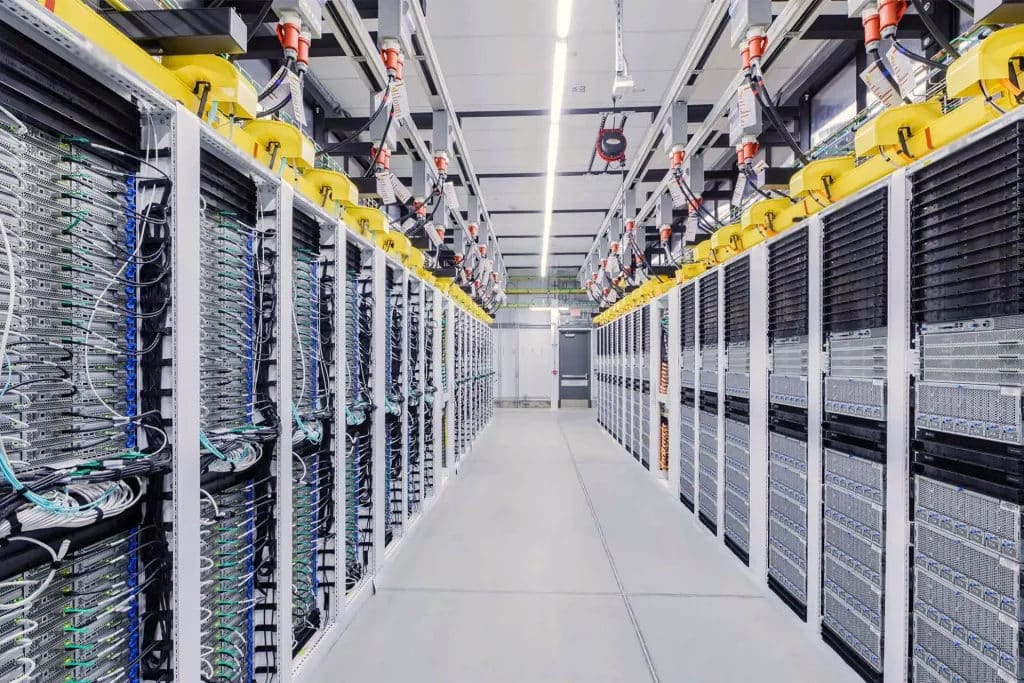
Silicon Carbide (SiC) is the premier choice for high-voltage, high-power applications, particularly in power factor correction (PFC) stages, solid-state transformers (SST), and front-end 800V rectification.
Thanks to its exceptional critical electric field and superior thermal performance, SiC ensures highly efficient and reliable conversion from MVAC to 800 VDC.
5. Non-Conventional Instrument Transformers (NCITs)
Traditional instrument transformers, current transformers (CTs) and voltage transformers (VTs), are essential for stepping down high grid voltages and currents to safe, measurable levels for protection relays and meters.
However, conventional oil-filled, iron-core units are massive, incredibly heavy, environmentally hazardous (due to oil leaks or explosions), and susceptible to magnetic saturation during severe fault conditions, which can distort the signal and cause relays to misoperate.
Non-Conventional Instrument Transformers (NCITs) represent a paradigm shift in grid measurement. Instead of relying on electromagnetic induction, NCITs utilize advanced optical or electronic sensing principles.
Figure 6 – High voltage optical current transformer (OCT)
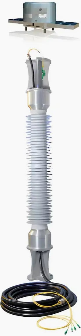
For current measurement, optical CTs (OCTs) typically employ the Faraday effect—where a magnetic field alters the polarization of light traveling through a fiber optic loop encircling the conductor.
For voltage, optical VTs (OVTs) use the Pockels effect, where an electric field changes the refractive index of an optical crystal.
They have a vastly wider dynamic range and do not suffer from magnetic saturation, ensuring highly accurate measurements even during the most extreme fault currents. They are significantly smaller and lighter than conventional units, simplifying substation design and reducing structural requirements. Furthermore, being completely oil-free and entirely passive at the high-voltage level, they dramatically improve substation safety and environmental compliance.
The adoption of NCITs is a critical step towards the fully digitalized IEC 61850 process bus architecture.
More in-depth – How to convert an old substation into a digital substation?
6. Modular, Preassembled Substations
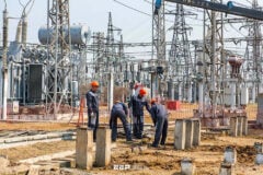
Historically, constructing a new medium or high voltage substation was a massive, bespoke civil engineering project. It involved extensive site preparation, pouring massive concrete foundations, erecting steel structures, and months of complex field wiring and testing in unpredictable weather conditions.
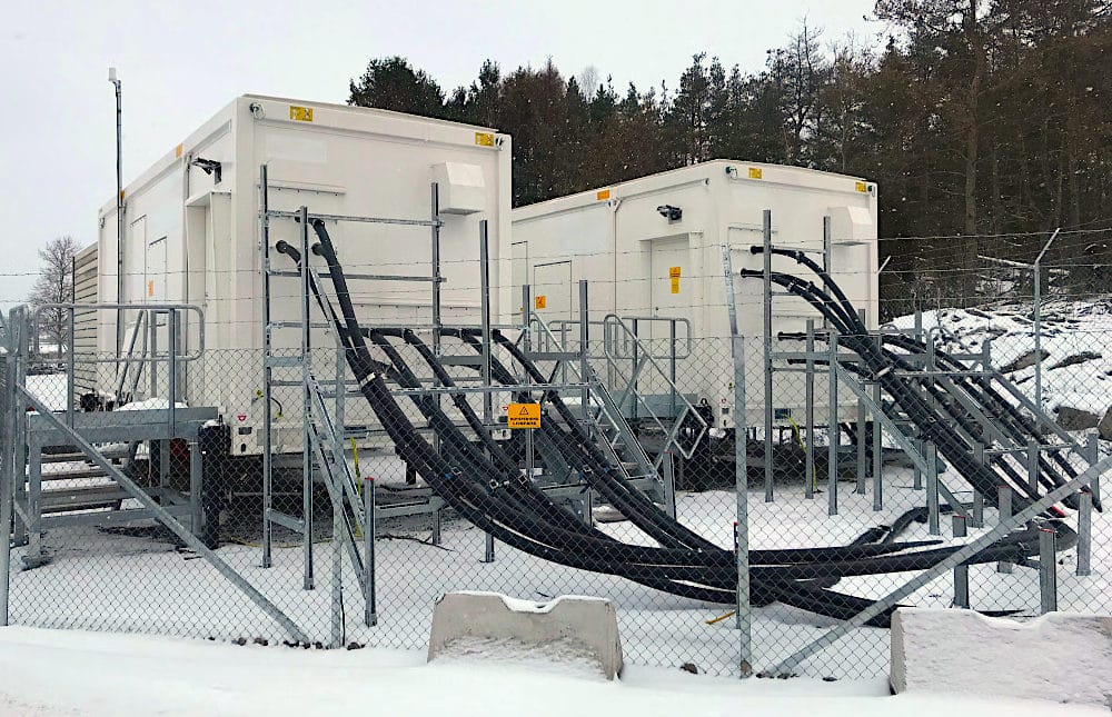
This traditional approach is costly, time-consuming, and highly susceptible to delays and quality control issues. In response, the industry is increasingly shifting towards modular, preassembled substation solutions.
The modular approach drastically accelerates project timelines. While civil site work is being completed, the substation is simultaneously being manufactured and tested off-site. Once delivered, installation often requires little more than bolting the modules to a prepared foundation and connecting the incoming high-voltage lines and external control cables.
This minimizes costly field labor, significantly reduces exposure to environmental hazards during construction, and ensures a much higher level of quality and reliability due to the rigorous factory acceptance testing (FAT) performed prior to shipping.
This trend is particularly vital for rapidly expanding grid infrastructure to support renewable energy projects in remote or challenging locations.
Figure 7 – Prefabricated Substations in Containers
7. Dynamic Line Rating (DLR) Sensors
The capacity of an overhead transmission line is fundamentally limited by thermal constraints. If too much current flows through the conductor, it heats up. Excessive heat causes the conductor to elongate and sag, potentially violating safe clearance distances to the ground or underlying structures, or in extreme cases, annealing and permanently weakening the metal.
Historically, utilities assigned Static Line Ratings (SLR), conservative capacity limits calculated based on worst-case, assumed environmental conditions (e.g., maximum summer temperature, zero wind, high solar radiation).
Dynamic Line Rating (DLR) technology solves this inefficiency by moving from assumed, static limits to real-time, dynamic limits based on actual physical conditions.
Figure 8 – The first US electric utility to integrate dynamic line ratings into real-time and market operations
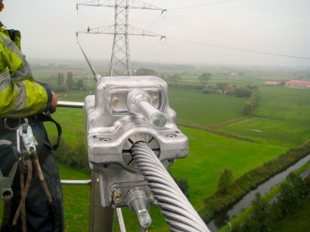
DLR systems utilize ruggedized IoT sensors clamped directly onto the live high-voltage conductors. These sensors continuously monitor critical parameters such as conductor temperature, sag, tension, and local weather conditions (ambient temperature, wind speed and direction, solar irradiance).
This real-time telemetry is transmitted back to the utility control center, where advanced algorithms calculate the true, real-time ampacity of the line.
This is a crucial, cost-effective tool for alleviating grid congestion and integrating variable renewable generation without the massive capital expense and lead times required to build new transmission lines.
Related electrical guides & articles



Edvard Csanyi
Hi, I'm an electrical engineer, programmer and founder of EEP - Electrical Engineering Portal. I worked twelve years at Schneider Electric in the position of technical support for low- and medium-voltage projects and the design of busbar trunking systems.I'm highly specialized in the design of LV/MV switchgear and low-voltage, high-power busbar trunking (<6300A) in substations, commercial buildings and industry facilities. I'm also a professional in AutoCAD programming.
Profile: Edvard Csanyi