
Estimated Study Time: 35 minutes
Protection equipment operation
Typically, protecting an electrical system, low-voltage, medium-voltage, or high-voltage, whichever it is, does not entirely depend upon a single component. The protection system is often a coordinated combination of multiple switching and protection units working in tandem to acquire the desired level of protection and reliability. The units or components are assembled inside a panel or dwell independently based on the uses and construction.
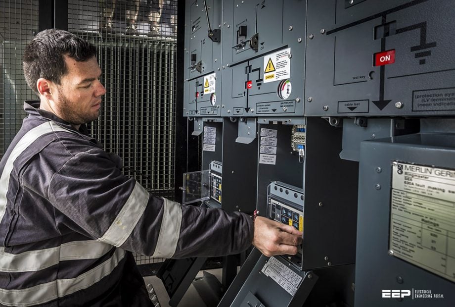 Dos and don’ts in operating LV/MV circuit breakers, relays, disconnectors and fuses (photo credit: RJ Power Group)
These assembled panels, units, and components find their use in power-generating substations, utility power distribution substations, private end usage substations, industrial plants, and any other places that are based on the utilization of electrical energy.
We often keep the components like circuit breakers, fuses, relays, switches, etc. in a single bracket of protection elements. In this article, we will analyze them from a fresh perspective. Despite being more or less similar in terms of primary function how these elements hold the character of their own and require a special procedure to operate perfectly.
The article describes how the protection zone, operating sequences, voltage level, and other multiple factors affect switching equipment operation and what we should or should not do while operating them.
- Criteria of selecting switching elements
- Switching elements in medium voltage networks
- Switching in low voltage networks
- Protection coordination
- Let’s summarize it
1. Criteria of selecting switching elements
1.1 Voltage level and power rating
Based on the voltage level and primary function, the type and number of switching elements vary in a substation. For instance, for an MV/LV utility power distribution substation, the major focus is on the flexibility of operation, selectivity, future expandability, and sufficient protection level.
Likewise, for private power distribution setup for commercial or industrial buildings, the focus shifts towards more controllability, frequent switching operation, and utmost protection level. Future expansion may not be of prime focus in these facilities. These factors bring subtle changes in the types and numbers of switching elements installed.
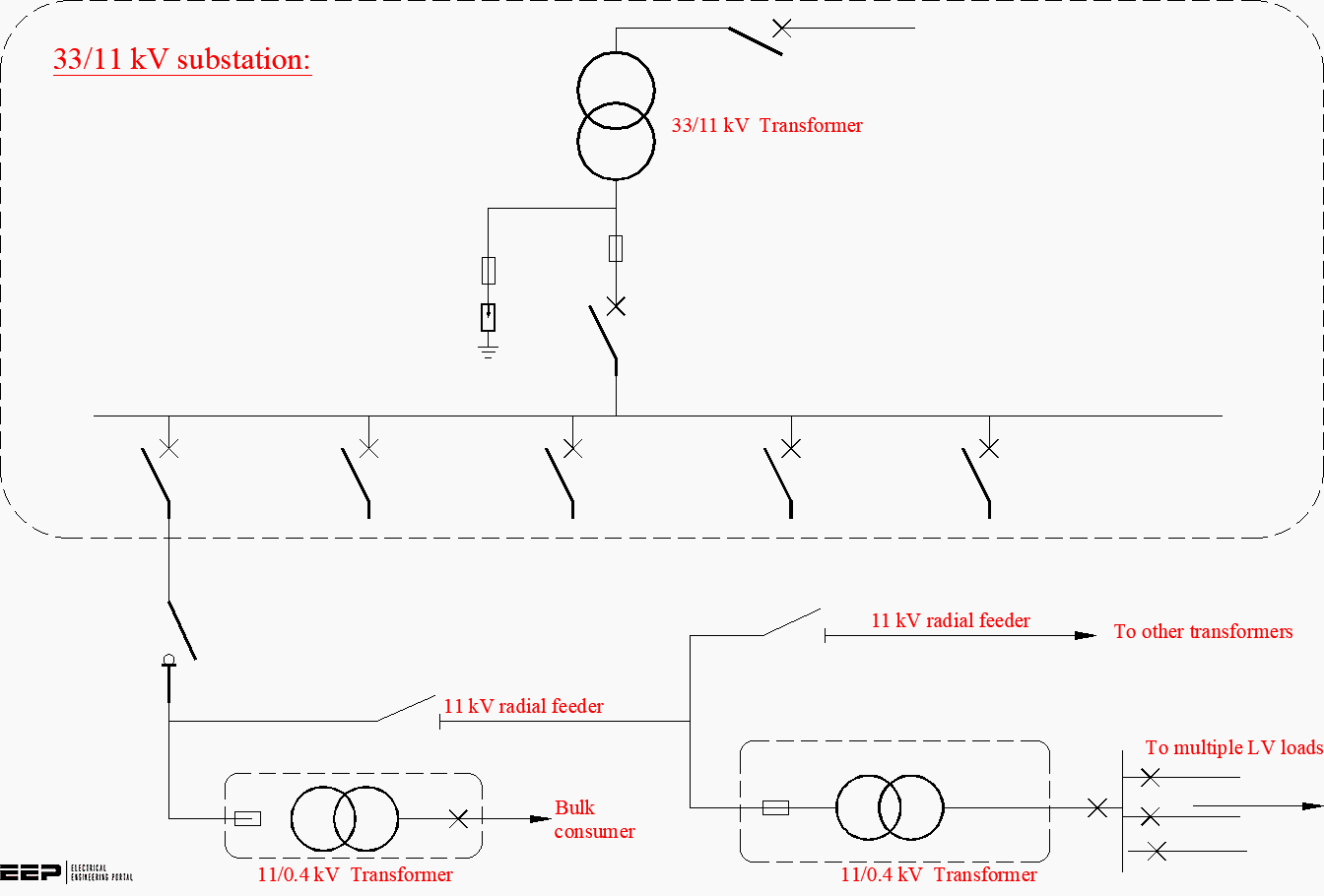
Figure 1 – An example of switching elements in 33/11 kV substation
The switching elements are designed to work up to the upper limit of the maximum system voltage because, barring exceptions of some fuses, all high voltage switching elements are zero-current interrupters. The system voltage is the most important deciding factor of switching element selection that helps to determine the dielectric stress on the switching devices while breaking the circuit.
The rated power or rated current of the switchgear also affects the selection of protection elements in the LV/MV power distribution system. For instance, in the LV system, heavy-duty MCCBs control the power distribution for maximum rated current up to 800A, while for anything higher than that, ACBs are better preferred.
Likewise, rated short-circuit breaking current, making current, peak withstand current, etc. all play their part on switchgear selection.
Related electrical guides & articles


Bishal Lamichhane
Electrical Engineer (B.E Electrical, M. Sc Engineering) with specialization in energy systems planning. Actively involved in design and supervision of LV/MV substations, power supply augmentations and electrification for utilities and bulk consumers like airports and commercial entities. An enthusiast and scholar of power systems analysis.Profile: Bishal Lamichhane
