
System Power Flow
A solar (PV) plant consisting of arrays will output power to a grid-tied power substation. The output of the plant is 60 MW. The solar power plant will produce DC current which is routed through a set of series/parallel conductors to an inverter.
The inverter outputs three phase AC current to a step-up transformer.
The step-up transformer outputs to a collector in the substation component, in which flows to the collector arrangement, feeder arrangement and key protection component. Finally, it is fed to the grid at 115 kV.
Substation Component Design
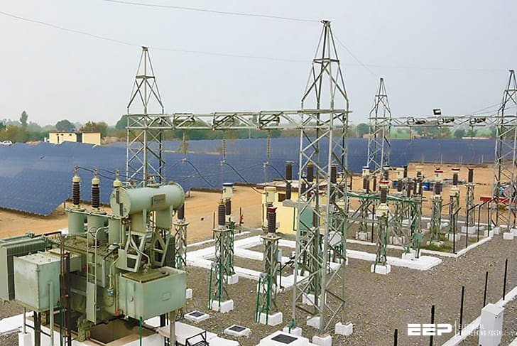
The purpose of the substation is to collect all solar array power and feed into the grid after stepping up voltage to distribution level. This substation is based on an Arcadia design, modified for the project.
Power flow is bottom to top, 34.5 kV bus to 115 kV bus. It will consist of the following major drawings (single-line drawings).
- Collector – Input from solar arrays’ transformer.
- Feeder – Output from collector, input to 34.5 kV bus.
- Key Protection – Circuit breakers, protection relays, capacitor bank, and step-up transformer. Outputs to grid at 115 kV.
The power flow block diagram in Figure 1 shows the input current flow from array skids. Array skids contain the inverter and step-up transformer. Power flow is bottom to top.
Substation Component Functions
Primary Transformer – The primary transformer is an 85 MVA that steps up the feeder bus input of 34.5 kV to desired 115 kV
Current Transformer (CT) – Drops current to manageable level for relay, usually between 1 and 5 amps.
Circuit Breakers – A device in key protection that opens the feeder switch when relay detects an overcurrent condition.
Relays – Relays are monitoring devices used to detect ground fault currents and reduce saturation.
Capacitor Bank – The 9.0 MVAR capacitor bank stabilizes harmonics associated with threephase currents and helps maintain a power factor of 0.95. Component specifications were provided by utility and Black & Veatch.
Surge Arrestor – Surge Arrestors are devices that are used to maintain equipment protected from overvoltage transients caused by lightning strikes, or switching over voltages within the substation itself. In this project they are used to protect the four terminals going into each of the three feeder transmission lines.
| Title: | 60 MW grid tied solar power plant with an attached 115 kV /34.5 kV substation – Black & Veatch |
| Format: | |
| Size: | 1.9 MB |
| Pages: | 40 |
| Download: | Here 🔗 (Get Premium Membership) | Video Courses | Download Updates |
Further Study – Dos and don’ts in operating LV/MV circuit breakers, relays, disconnectors and fuses
Dos and don’ts in operating LV/MV circuit breakers, relays, disconnectors and fuses

I have a projet 5MW solar energy. What station need to conect a 34.5 line?
My institution is trying to get the cost of Building our own sola power station to power our campus. Our power consumption presently is about 10MGWATTS.
The institution is the University of Port Harcourt, Port Harcourt Rivers State Nigeria.
Sorry, this is my contact for chatting, +2348055353282
For Project
i am interested on pv subject
voltage of power generated by solar PV power projects is 11kV?
hi/ It depends on the capacity of your PV plant . Normally 11 or 20 or 33 kV are seen.But please note that the output of the pv panels are DC low voltage e.g. 300 or 400 or 690V … depending on the voltage of the strings.
When I generate from solar plant, can I energyze the PT from the secondary?, I mean without voltaje from the 130kV substation?
No
1)In the single line diagram circuit breakers,P.T.s,L.As,Isolators,capacitor banks, auxilary transformer are not shown.
2)Capacitors,I think, are required to correct the inductive KVAr of the load system.For 85 MVA load PTR,more than 9 MVAr is required.
3)CTs and PTs are used both for metering and protection.
Boa coisa