
Control of drive systems
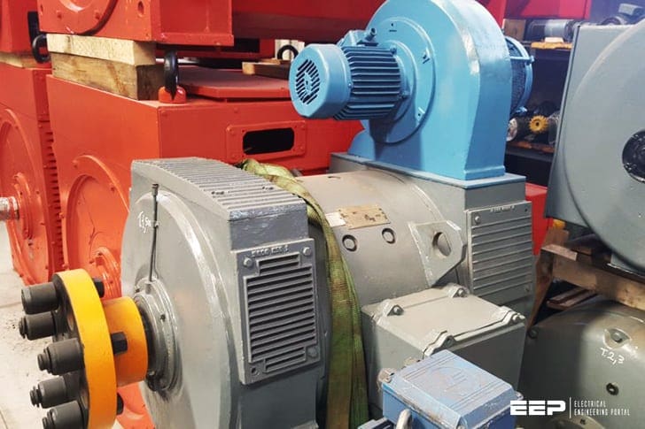
DC motors are widely used in many speed-control drives. Open-loop operation of DC motors may be satisfactory in many applications. When the load increases the speed of the motor drops and the new operating point of speed is obtained after the transient.
For getting constant speed i.e. the initial operating point the open loop does not work. So, closed-loop control system is required. The basic block diagram of closed-loop control system is shown.
If the motor speed decreases due to application of additional load torque, the speed error εN increases, which increases the control signal Ec . This in turn changes the firing angle of the converter, and thus increases the motor torque to restore the speed of the drive system.
The response of a closed –loop system can be studied by using transfer function techniques.
Separately Excited DC motor Drives
Armature voltage control is inherently a closed loop control system in DC motor drives. However, the output speed signal can not be measured and the speed error is not found properly.
This closed loop is further extended by using a feed back tachogenerator with speed controller and converter for modern control drives.
Solid State Control
DC motor speed control by solid state can be done by two methods: DC-DC Chopper control and Phasr rectifier control method.
Chopper control of Dc motor drive: (separately excited)
This is one of the simplest power-electronic/machine circuits. With a battery, it is currently the most common electric road vehicle controller. The ‘chopper‘ is also used for some d.c. rail traction applications.
The principal difference between the thyristor-controlled rectifier and the chopper is that in the former the motor current always flows through the supply, whereas in the latter, the motor current only flows from the supply terminals for part of each cycle.
The chopper may use transistor, thyristor, MOSFET or IGBT as switches.
A single-switch chopper using a thyristor can supply positive voltage and current to a DC motor, and is therefore restricted to quadrant 1 motoring operation. When regenerative and/or rapid speed reversal is called for, more complex circuitry is required, involving two or more power switches.
Function:
Vdc = V,CH1 on
Vdc = 0,CH1 off
D1 on
| Title: | Lecture notes in electrical drives and traction systems – A course in 7th semester of Bachelor of technology programme in electrical engineering by Department of Electrical Engineering Veer Surendra Sai University of Technology, Burla |
| Format: | |
| Size: | 2.00 MB |
| Pages: | 65 |
| Download: | Here 🔗 (Get Premium Membership) | Video Courses | Download Updates |

im interested this topic