
Centrifugal Pumps & Variable Frequency Drives
The Pump Essentials
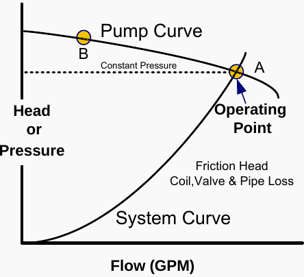
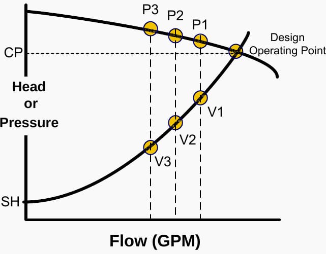
The affinity laws are applicable to pumps in the same manner as they are to fans. To comprehend Variable Frequency Drive (VFD) applications in pumps, it is advisable to examine the fundamental principles of pump utilization. Figure 1 illustrates a pump curve in relation to a hydronic system curve. The pump curve delineates the relationship between “head” (or pressure) and flow characteristics of a certain pump.

The curve indicates that the pump will yield restricted flow at point “B” when utilized in a system necessitating a substantial differential pressure to elevate the water/glycol and surmount flow resistance. Increased flow rates are attained with this pump when the pressure differential is diminished, as observed at point “A”.
Identifying the operational point of the pump on the pump curve necessitates data from the system curve. The system curve illustrates the attributes of the piping system. It illustrates the increase in “friction head” corresponding to flow rate.
Friction head quantifies the resistance to flow imposed by pipes, valves, elbows, and other system components.
Figure 1 – Pump curve relative to a hydronic system curve
Static Head
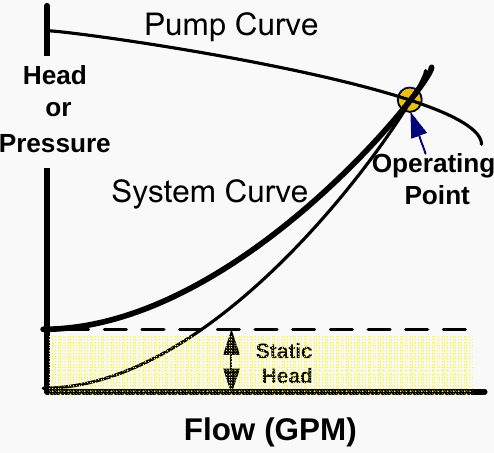
The head needed with zero flow is referred to as static head or lift. Figure 2 illustrates the combined friction and static head curve for the system. The static head refers to the height in feet that the pump must raise the water, independent of flow rate. Another perspective is to consider it as the effort required to counteract gravity.
The convergence of the pump and system curves indicates the fundamental or designated operating point for the system. The pump pressure currently equals the system losses.
The intersection would typically be selected to guarantee that the pump operates at or near its optimal efficiency.
Figure 2 – Combined friction and static head curve for the system
Flow Control
Two-Way Control Valves
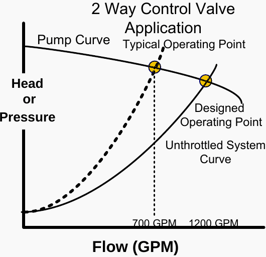
Most hydronic systems do not consistently operate under design circumstances. Systems equipped with 2-way control valves regulate flow by adjusting the valve to different positions. Closing the valve diminishes flow and elevates friction inside the system.
Figure 3 illustrates a standard operating point attained when a specific flow is obtained by the control valve. Observe that the flow is attained, albeit at an elevated system pressure.
See Figure 3.
Figure 3 – Typical operating point when a particular flow is achieved by the control valve
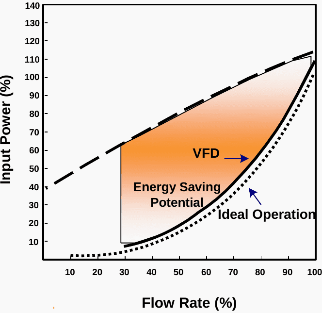
Pump Energy Savings With VFDs
Utilizing a VFD on a pump to decrease speed and consequently flow results in a downward shift of the pump curve, as illustrated in Figure 4. The operating point remains at the newly adjusted pump curve and system curve, resulting in the same reduced flow of 700 GPM, down from 1200 GPM, as observed with a valve.
This flow is attained, albeit at a diminished pressure. Operating under diminished pressures can lead to an extended lifespan of pump seals, less impeller degradation, and minimized system vibration and noise.
See Figure 5.
Figure 4 – Applying a VFD to a pump to reduce speed and flow causes the pump curve to shift down
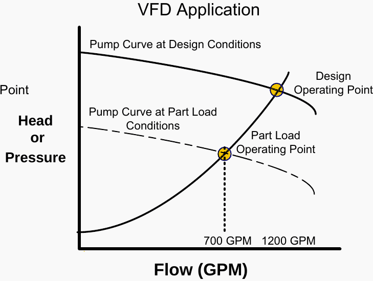
Figure 5 – Due to the affinity laws, power is greatly reduced at reduced flows
Applying VFDs To Pumps To Realize Savings
Similar to most HVAC systems, original pump designs may be predicated on worst-case maximum flow scenarios for potential future expansion, or the designer may have applied the standard 15 to 20% over-sizing criterion. When assessing VFD retrofit prospects for energy conservation, one should examine the system and pump curves and analyze the current flow modulation mechanism.
See Figure 1.
- BYPASS: If bypass control is employed (for instance, a 3-way valve at the coils), the system maintains a consistent pressure at all times. Refer to ‘CP’ in Figure 6. The potential for savings can be substantial in the absence of modulation when retrofitting VFDs.
- 2-Way VALVE CONTROL: The system operates throughout the pump curve from the Operating Point to P3 when 2-way valves are utilized. These systems consume less energy than constant pressure systems.
If a VFD is utilized, the system will run along the system curve from the Operating Point to V3.
Figure 6 – Applying VFDs To Pumps To Realize Savings
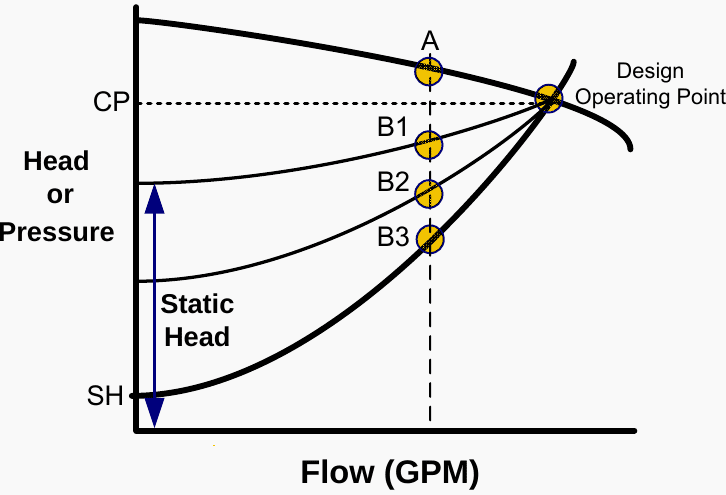
Static Head
Static head can influence potential energy savings. If the static head is elevated, the system curve may approximate a constant pressure. Figure 7 illustrates a pump curve accompanied by three system curves: one representing zero static head and two others with varying static heads. The disparity between points A and B indicates potential energy savings for a specified flow rate.
The lower the static head, the larger the potential energy savings with variable frequency drives (VFDs).
Figure 7 – Three system curves: one with no static head, and two others different static heads
Determining Pump & System Curves
Pump curves are easily obtainable from manufacturers, whereas system curves are more challenging to ascertain. A rapid technique to estimate the curve:
- Determine the un-throttled (open) system flow rate at the location under consideration. (you may need to measure this at different locations or have a balancer establish this for you)
- Measure the static head
- Plot these two points on a copy of the pump curve.
- Connect these points using a square function : Head = Flow2
| Title: | Practical guide to Variable Frequency Drives (VFDs) in retrofit and new applications by Yorkland Controls Ltd |
| Format: | |
| Size: | 20.8 MB |
| Pages: | 36 |
| Download: | Right here | Video Courses | Membership | Download Updates |
Suggested (PDF) – A practical handbook for electrical engineers (beginners)
