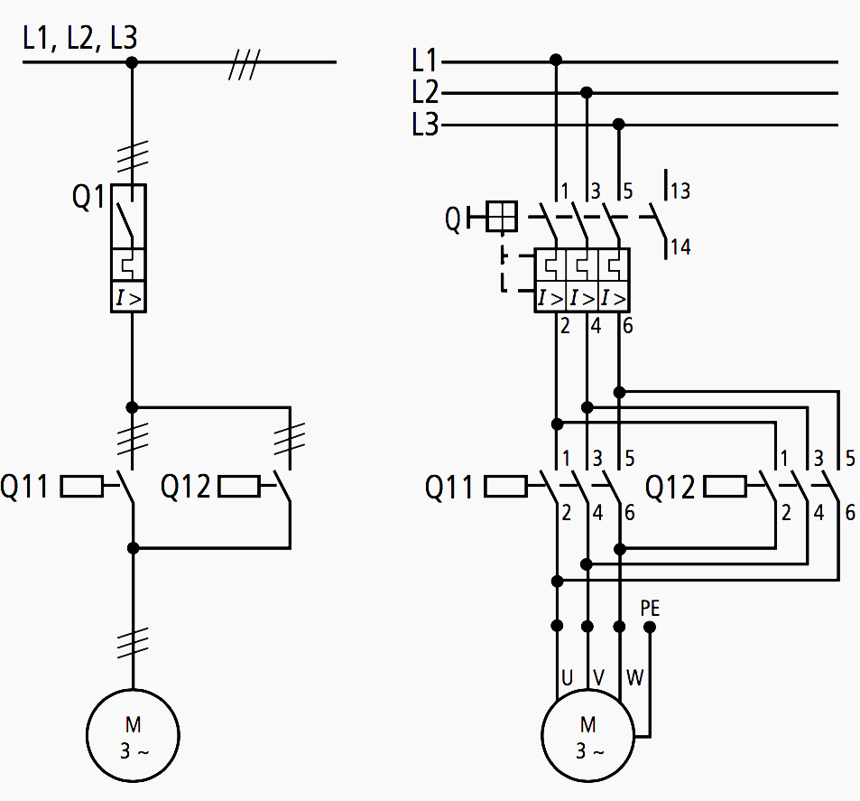
Motor circuit diagrams
Diagrams indicate the voltage-free or current-free status of the electrical installation. A distinction is drawn between:

Block diagram – Simplified representation of a circuit with its main parts. It shows how the electrical installation works and how it is subdivided.
Circuit diagram – Detailed representation of a circuit with its individual components,which shows how the electrical installation works.
Equivalent circuit diagram – Special version of an explanatory circuit diagram for the analysis and calculation of circuit characteristics.

Motor wiring diagrams
Wiring diagrams show the conductive connections between electrical apparatus. They show the internal and/or external connections but, in general, do not give any information on the mode of operation. Instead of wiring diagrams, wiring tables can also be used.
Unit wiring diagram – Representation of all the connections within the device or combination of devices.
Interconnection diagram – Representation of the connections between the device or combination of devices within an installation.
Terminal diagram – Representation of the connection points of an electrical installation and the internal and external conductive connections connected to them.
Location diagram (location diagram) – Representation of the physical position of the electrical apparatus, which does not have to be to scale. You will find notes on the marking of electrical apparatus in the diagram as well as further diagram details in the chapter “Specifications, Formulae, Tables”.
| Title: | All about wiring of electric motors – EATON |
| Format: | |
| Size: | 1.2 MB |
| Pages: | 102 |
| Download: | Here 🔗 (Get Premium Membership) | Video Courses | Download Updates |


that is good page
Interesting in knowing more about the field of Electrical Electronics engineering
Hi, so I have been looking and reading up on as many topics as I can for the knowledge, I am currently in a planning phase of turning motors in to generators, looking into what I need to do insure that generated voltages can be combined and ultimately made into a grid for household back up, or powering accessory items in my home without using municipal power. Can 3 phase power be manipulated in such a way that could be applied to 1phase use?
I have a dream of making power generator as well as a system that would drow water from a well as a combined system any advice please would help me alot