Choice of thermostatic valve size / Existing one-pipe systems
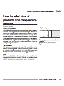
All the radiators must be equipped with thermostatic valves to be able to control the room temperature, use the incidental heat gain efficiently and distribute the heat according to requirements. This requires a by-pass at each radiator, and the resistance in the by-pass has to be larger than in the main pipe so that a certain amount of water is let to in the radiator.
Good operation is obtained if the thermostatic valve has a low resistance, like valves intended for gravity circulation, and the by-pass is of the same dimension as the main pipe. The by-pass is equipped with a restriction creating the required resistance.
Two-pipe systems
The valve size is determined on the basis of the required flow and the available differential pressure. Maximum differential pressure is limited to 25 kPa as far as noise is concerned. The available differential pressure for each thermostatic valve is obtained from the pipe calculation.
Flow
The flow is calculated from the heat requirement in watts, W, and the temperature drop across the radiator in Kelvin, K. The valve size can then either be determined from a selection flow chart or be calculated.
Valve size
The last valve in the design circuit, (which determines the pump head throughout the entire system) ought to have a resistance of about 5 kPa.
The other valves should be sized according to the differential pressure available for them, i.e. the penultimate valve in the design circuit has an available pressure equal to the resistance across the last valve plus the resistance in the pipes between the two valves.
| Title: | 8 STEPS – CONTROL OF HEATING SYSTEMS – Part 7 – How to select size of products and components |
| Format: | |
| Size: | 0.9MB |
| Pages: | 22 |
| Download: | Right here | Video Courses | Membership | Download Updates |


