
Surge Arresters & Lightning Flashover
This guide discusses the application of arresters on transmission lines to improve lightning flashover rate. A lightning flashover on a transmission line requires breakers operation to eliminate the resulting short-circuit resulting in a voltage interruption. This voltage interruption can be a short duration one if the line has a fast reclosing sequence.

Even if it is of short duration, the momentary voltage dip represents a major concern for customers as equipment or process are nowadays more sensitive than in the past to short interruptions. If flashover occurs on both circuits of a double circuit transmission line, the impact can be very detrimental.
Utilities are well aware of the problem and are looking to all possible solutions to improve the situation.
Metal Oxide (MO) arresters are voltage limiting devices that appeared on the market at the end of the 1970s. Since then, they have been widely used on power systems and proved their increased robustness, energy absorption capacity and reliability compared to Silicon Carbide (SiC) gapped arresters used in the past on distribution lines.
Field performance of the installed line arresters has been very good for the most part although mechanical failure rates in some regions are high. The guide presents in §3 the main reasons for line arresters installation.
Figure 1 – Typical mounting structures of EGLA (left: 77kV transmission line; right: 500kV line)
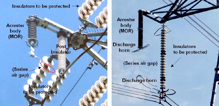
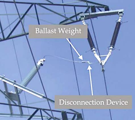
The arresters installed in parallel with the insulator strings are of two different types, as it is presented in §4. One type, called “gapless”, Non-Gapped Line Arrester (NGLA), has a normal rating for the service voltage level and its design is similar to the substation arrester. It is equipped with a special disconnector to allow line reclosing and power supply availability in case of arrester failure.
The other type, called “gapped”, Externally Gapped Line Arrester (EGLA), is equipped with an external series air gap that sparks over only when a lightning overvoltage of sufficient magnitude occurs on the line. The gap eliminates flexible connections to ground, and allows the rating of the arrester to be reduced.
In case of an arrester failure line reclosing should be successful as the air gap is designed to withstand the resulting switching overvoltages. Each type of arresters has advantages and inconveniences that will be described later in this guide.
The last part of the guide is devoted to the presentation of different case studies illustrating the main application of line surge arresters.
Figure 2 – Line arrester with a disconnection device mounted on a 110 kV tower
What is a surge arrester?
A surge arrester is a protective device that limits overvoltages on a power system to protect equipment by discharging or bypassing surge current. Its protective level may be selected to limit only lightning overvoltages, in the case of a typical line surge arrester, or it may also conduct during switching surges or temporary overvoltages.
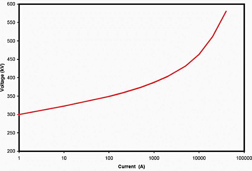
NGLA limits the power frequency flow current to less than a few mA under normal service voltage after any overvoltage. It is able to repeat the overvoltage protection function many times. It has a non linear voltage-current characteristic, typically varying as V=kI1/α with α between 5 and 50, permitting to discharge high magnitude surge currents while limiting voltage to a safe value.
EGLA having a series air gap do not conduct power frequency current but provides the same voltage limiting characteristic after flashover of the air gap.
Figure 3 – Voltage-Current characteristic of a NGLA
When surge arresters are installed in parallel with insulator strings (see Figure 4) the arresters are selected to limit the voltage along the insulator strings below their flashover voltage. This avoids flashover of the protected insulator and the air gaps between the protected conductors and the tower. The current conducted by the arrester during this protection function raises the voltage of the protected phase conductor, and a fraction of this voltage is coupled by mutual surge impedance to nearby unprotected phases.
The improved coupling, achieved by adding an additional overhead groundwire in parallel with those already existing, affords an additional benefit in reducing the back flashover rate of the unprotected phases, as it will be discussed later in next paragraph.
The next paragraph will give some basic insight on lightning overvoltages occurring on overhead lines and the different possible methods to limit the number of lightning flashovers on overhead transmission lines.
Figure 4 – Installation of line surge arresters on a 90 kV tower

Lightning stroke impacts on a phase conductor, a tower, or a shield wire
Flashovers due to shielding failure
Even if a line is protected by shield wires, it is still possible that a lightning stroke of low current magnitude terminates on a phase conductor. This mostly happens if the so-called protection angle exceeds a given value or if the first lightning stroke current has a low amplitude. This phenomenon, called shielding failure, could be a direct root cause of flashover of insulator strings.
Shielding failures may result or not in flashover, depending on the amplitude of the lightning current and on the LIFV. Further, one needs to take into account that a large percentage of first strokes are followed by subsequent flashes with a current sufficient to cause flashover, which may result in flashover of an unprotected insulator.
Figure 5 – Representation of the lightning current including a first stroke (higher magnitude) and a subsequent stroke
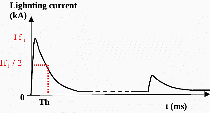
For this reason shielding failure is considered to be a problem. The rapid decay of voltage (chop) at the time of flashover is at the origin of severe overvoltage stresses at line terminals.
Figure 5 represents the typical shape of a lightning current. In case of shielding failure, the crest value of the lightning current is equal to a few kA only. Lightning currents of higher magnitude will generally be intercepted by the shield wires as illustrated by electrogeometric models.
| Title: | Application Guide for Surge Arresters in Lightning Protection of Transmission Lines – Working Group C4.301, Cigre |
| Format: | |
| Size: | 1.6 MB |
| Pages: | 50 |
| Download: | Here 🔗 (Get Premium Membership) | Video Courses | Download Updates |
Further Study – Design of Auto/Manual Changeover Logic Between Two Busbars
Design of Auto/Manual Changeover Logic Between Two Busbars Within a Substation
