
Wiring diagrams
Wiring diagrams show the connections to the controller. Wiring diagrams, sometimes called “main” or “construction” diagrams, show the actual connection points for the wires to the components and terminals of the controller.
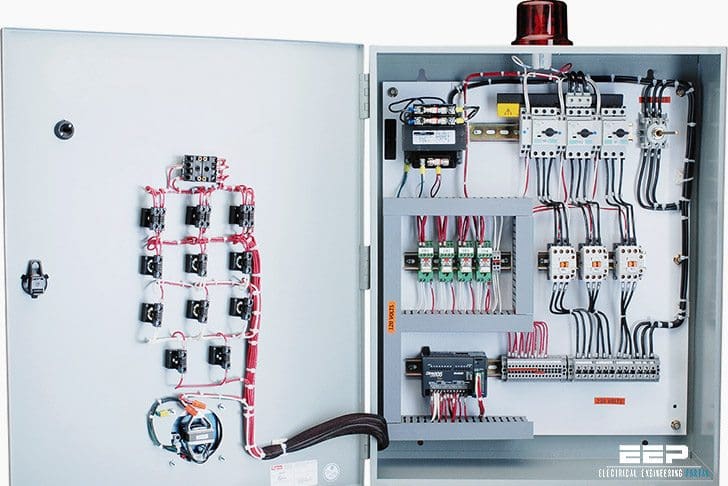
They show the relative location of the components. They can be used as a guide when wiring the controller. Figure 1 is a typical wiring diagram for a three-phase magnetic motor starter.

Line diagrams show circuits of the operation of the controller
Line diagrams, also called “schematic” or “elementary” diagrams, show the circuits which form the basic operation of the controller. They do not indicate the physical relationships of the various components in the controller. They are an ideal means for troubleshooting a circuit.
Figure 2 shows a typical line or schematic diagram.

Standardized symbols make diagrams easier to read
Both line and wiring diagrams are a language of pictures. It is not difficult to learn the basic symbols. Once you do, you are able to read diagrams quickly, and can often understand a circuit at a glance. The more you work with both line and wiring diagrams, the better you will become in analyzing them.
Because of these standards, you will be able to read all diagrams that come across your workbench.
| Title: | Basic Wiring for Motor Contol – Technical Data // EATON |
| Format: | |
| Size: | 946 KB |
| Pages: | 14 |
| Download: | Here 🔗 (Get Premium Membership) | Video Courses | Download Updates |


The control switch for an electric hoist I have was pulled out of the wiring harness on the motor. One of the 4 wires was broken so that reconnection is obvious. The other 3 wires were pulled out of the wiring harness. If I send you pictures of the wiring diagram on the underside of the harness cover and pictures of the harness and wires could you tell me which or the three unconnected wires plug into which of the 4 harness locations?
Many Thanks
Hi,
I purchased used motorized honey extractor. The motor is not working and there is no smell also i had rradings on multimeter.
Can you please help me figure out which wire goes where because the seller had it wired wrong.
Much appreciated
Regards
Very straight forward and I would like to see the wiring diagram and any more detailed on how the indicator lights are integrated.
Protection and Automation Engineers
Helpful
whats the price of this motor control panel
Pls can you please send e a material that will help me to connect a pump to as panel then to a HMI
domestic wiring and motor control
pls send me some information
Hay bos, thanks to this articles, btw can i reshare this with my language?
Knowledge of basic single- and three phase electrical systems including basic AC and DC motor control and safety measures on electrical equipment.
Really helpful
Wow. Fantastic stuff here.
Should have a fuse on control circuit and possibly show a transformer for control circuit in which more often than not one is used
Really is the best college for practical knowledge base learning
It is good keep it up
thanks a lot, truly it’s helpful
Thank you the information is very useful
i feel so appreciated for your efforts
thank you for this service its very useful for me
Good information
Thank you very much I really enjoyed it
it is a good knowledge for learning.
I’ve known the control but the question is how do you actually connect the 3 wires coming from overload relayinto the connection box of the motor if it has 3 leads or 6 leads?
Thanks..
Depending on your motors application (low or high voltage).
In a 480vac application you’d wire the wires inside of the box 4-7 5-8 6-9… The 3 phases coming into the box from your overload would pair with wires 1,2,3 inside of the box.
Best site for learning
thanks , its really help full for me . please help me to understand more circuits on panels
thank u very much
Thank you so much!! This is helpful!! I am glad to be part of this site!!