Earthing systems and their materials
Individual foundations
Each individual foundation, such as those for supports, must be equipped with a foundation earth electrode that has a minimum length of 2.5 meters. The foundations must be electrically interconnected, and the maximum dimensions of the loop should not exceed 20x20m. It is necessary to guarantee the corrosion resistance of both the individual foundations and the conductors by employing appropriate methods and materials.

Foundation earth electrode
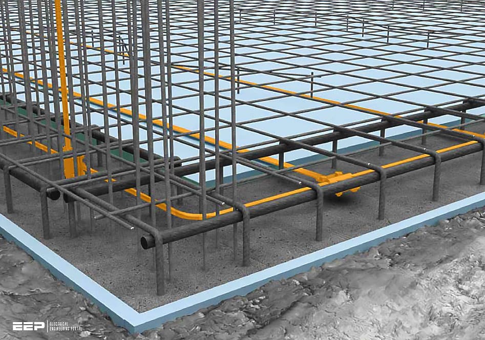
A foundation earth electrode is a closed loop, ideally composed of flat conductors or, alternatively, round conductors, with a maximum width of 20×20m. The foundation earth electrode is linked to the reinforcement by clamp connectors, with a separation of approximately 2 meters. In order to guarantee corrosion prevention, the foundation earth electrode should be securely implanted in the concrete with a minimum coating thickness of 5 cm.
The concrete facilitates the establishment of the electrical connection between the foundation earth electrode and the earth.
Insulating the concrete eliminates the requirement for an electrical connection to the earth. The insulation facilitates significant desiccation of the concrete. For instance, this applies to variations such as a black tank with perimeter insulation or a white tank.
In order to maintain a consistent earthing resistance, the ring earth electrode should be securely connected to the earth in an area outside the foundation that is moist and free from frost. This factor should be given special consideration, especially when dealing with extensive roof projections.
To address this situation, it is necessary to employ a ring earth electrode either outside or underneath the concrete foundation. The ring earth electrode, which is in direct touch with the earth, is connected to the functional equipotential bonding conductor of the foundation.
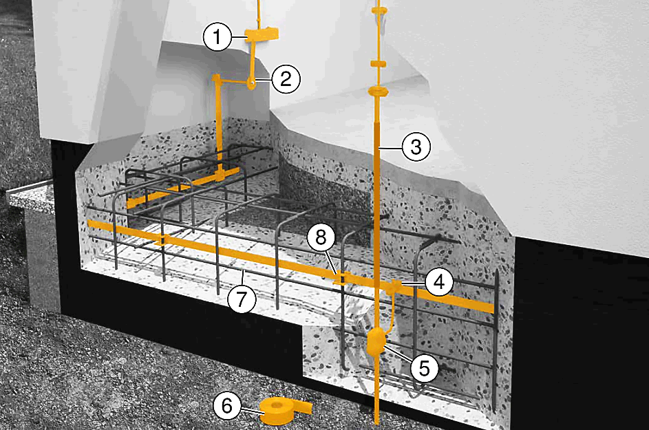
Figure 1 – Type B foundation earth electrode

Where:
- Main equipotential busbar (MEB)
- Earthing fixed point
- Earth entry rod
- Cross-connector
- Cross-connector with corrosion protection
- Corrosion protection strip
- Flat conductor
- Connection terminal for reinforced steels
Systems that have demanding electromagnetic compatibility (EMC) requirements necessitate a robust foundation earth electrode. To minimize impedance, the loop diameter is typically reduced to 5×5m instead of the standard 20×20m (as specified in VDE 0185-305-4/IEC 62305-4).
Steel fibre concrete floor plates fail to meet corrosion protection standards when covered with a 5 cm layer of concrete. Prior to the process of concreting, it is necessary to construct a ring earth electrode made of high-quality stainless steel V4A (1.4404/1.4571).
It is important to ensure that connections in the soil are safeguarded using a corrosion protection strip.
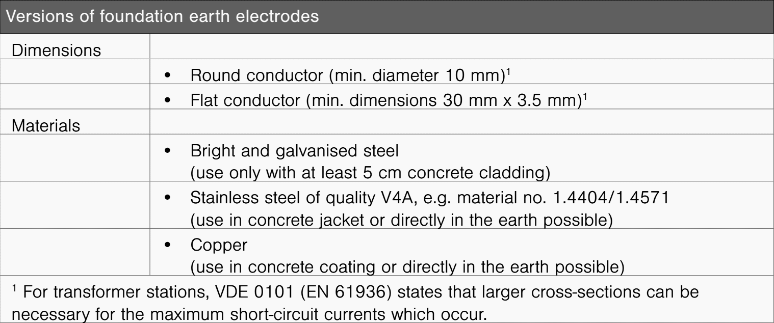
Table 1 – Versions of foundation earth electrodes

All metals in contact with the ground or water can corrode. Electrochemical corrosion occurs when different metals are connected with one another in soil, water or molten salt.
It can also occur when a single type of metal is embedded in two distinct environments, e.g. steel in earth and concrete.
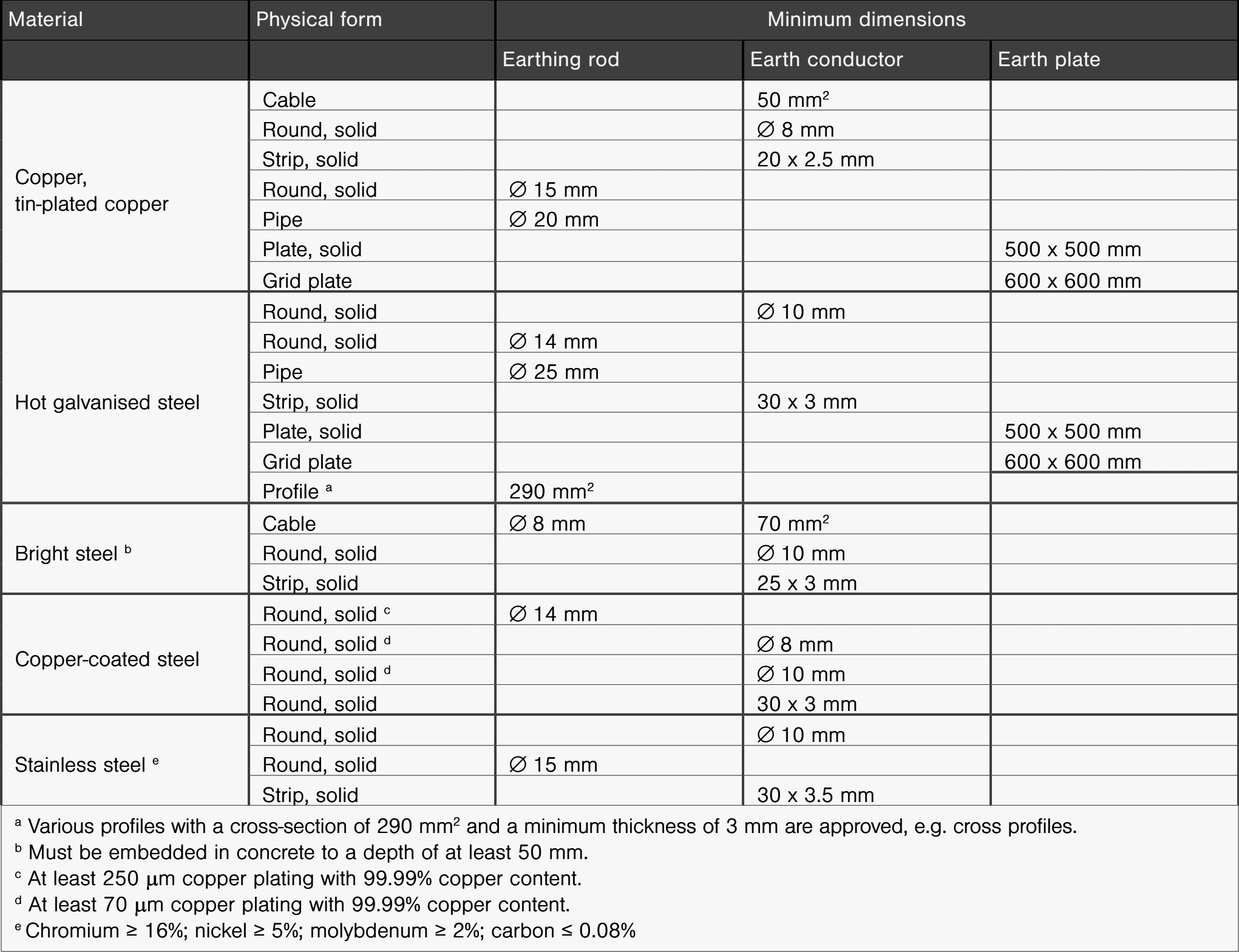
Table 2 – Materials, form and cross-section according to VDE 0185-561-2 (IEC 62561-2)

Insulated earthing systems
If the concrete is insulated, then there need be no electrical connection to the earth. The insulation means that the concrete dries out to a great extent. This is, for example, the case with the following versions:
- Perimeter insulation: Heat insulation on the underside and side walls of the foundations
- Black tank: Seals with bitumen strips or polymer-modified bitumen thick coating (KMB)
- White tank: Water-impermeable (WU) concrete to DIN 206-1 and 1045-2 of the quality C25/30
- Poorly electrically conductive earth strata, e.g. made of recycled material or crushed glass
If the earth electrode is installed under the floor plate of the insulated foundation, then the following loop width must be maintained:
- 10×10 m with lightning protection measures
- 20×20 m without lightning protection measures
For this reason, in large buildings, the earthing system must be installed before the concrete work.
Perimeter insulation
Perimeter insulation is created from heat-insulation plates and is used beneath floor plates and on cellar walls. The use of perimeter insulation does not create an electrically conductive connection between the concrete foundation and the earth.
Perimeter insulation surrounding on all sides. If all the walls, foundations and the bottom of the foundation are surrounded by the perimeter insulation of the structure, then the function of the foundation earth electrode will be restricted or non-existent.
Perimeter insulation only on the surrounding walls If the perimeter insulation is only on the surrounding walls, earth electrode contact is often still intact. The foundation earth electrode can be implemented in the concrete. To ensure contact with the earth, no water-impermeable concrete (WU concrete) may be used.
| Title: | A good guide on how the earthing system should be correctly implemented – OBO Bettermann |
| Format: | |
| Size: | 3.60 MB |
| Pages: | 24 |
| Download: | Right here | Video Courses | Membership | Download Updates |
Suggested – 8 common mistakes in reading and creating single line & wiring diagrams
Eight common mistakes in reading and creating single line and wiring diagrams

