DC Generator
The electrical machines deals with the energy transfer either from mechanical to electrical form or from electrical to mechanical form, this process is called electromechanical energy conversion.

An electrical machine which converts mechanical energy into electrical energy is called an electric generator while an electrical machine which converts electrical energy into the mechanical energy is called an electric motor.
A DC generator is built utilizing the basic principle that emf is induced in a conductor when it cuts magnetic lines of force. A DC motor works on the basic principle that a current carrying conductor placed in a magnetic field experiences a force.
Working principle
All the generators work on the principle of dynamically induced emf. The change in flux associated with the conductor can exist only when there exists a relative motion between the conductor and the flux. The relative motion can be achieved by rotating the conductor w.r.t flux or by rotating flux w.r.t conductor.
So, a voltage gets generated in a conductor as long as there exists a relative motion between conductor and the flux. Such an induced emf which is due to physical movement of coil or conductor w.r.t flux or movement of flux w.r.t coil or conductor is called dynamically induced emf.
Whenever a conductor cuts magnetic flux, dynamically induced emf is produced in it according to Faraday’s laws of Electromagnetic Induction. This emf causes a current to flow if the conductor circuit is closed.
So, a generating action requires the following basic components to exist:
- The conductor or a coil
- Flux
- Relative motion between the conductor and the flux.
In a practical generator, the conductors are rotated to cut the magnetic flux, keeping flux stationary. To have a large voltage as output, a number of conductors are connected together in a specific manner to form a winding.
The magnetic field is produced by a current carrying winding which is called field winding. The conductors placed on the armature are rotated with the help of some external device. Such an external device is called a prime mover. The commonly used prime movers are diesel engines, steam engines, steam turbines, water turbines etc.

Induced emf
The nature of the induced emf for a conductor rotating in the magnetic field is alternating. As conductor rotates in a magnetic field, the voltage component at various positions is different. Hence the basic nature of induced emf in the armature winding in case of dc generator is alternating.
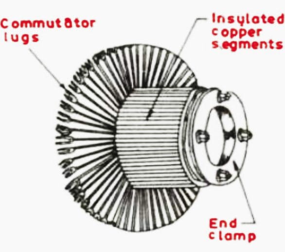
To get dc output which is unidirectional, it is necessary to rectify the alternating induced emf. A device which is used in dc generator to convert alternating induced emf to unidirectional dc emf is called commutator.
| Title: | The Essentials Of Electrical Machines – JNTU World |
| Format: | |
| Size: | 22.1 MB |
| Pages: | 75 |
| Download: | Here 🔗 (Get Premium Membership) | Video Courses | Download Updates |


This article contains essential partrs of Electro-mechanical Energy conversion that should be known by a practising electrical engineer. Chapters on Synchronous machines, Single phase motors and a brief intro to generalized theory are missing. This probably would be the third semester part which is not out yet. However the formulae in this article, especially the integral and differential formulations or even simple ratios, do not appear correctly, some figures are poor and in general the whole text is hardly readable as yet. The references at the end (Fitzgerald & Kingsley and M. G. Say) are classics.I would also like to add Adkins and Harley on the general theory.
What a nice picture…!
The download link on this article is currently linked incorrectly. 12/6/2017
It’s fixed now, thank you!