Electrical equipment in power plants
Without having knowledge about electrical equipment, power generation from the power plant is difficult to understand. Hence it is necessary to have an idea about the role of electrical equipment. The purpose of this guide is to introduce the students to the electrical equipment used in power plants. The main electrical equipment is generator and generator cooling, transformers and their cooling, busbars, exciters, reactors, circuit breakers, switchboard, and control room equipment.

Generator and motors
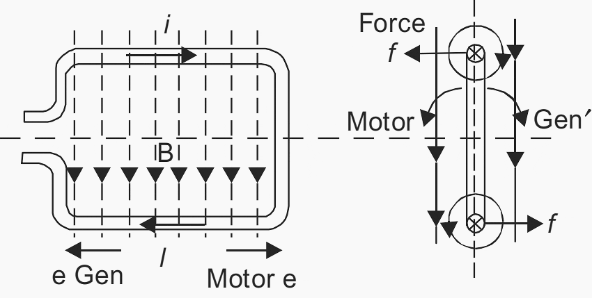
In a generator, an e.m.f. is produced by the movement of a coil in a magnetic field. The current produced by the e.m.f. Interacts with the field to produce a mechanical force opposing the movement, and against which the essential movement has to be maintained. The electrical power is produced therefore from the mechanical power supplied.
In a motor, we may suppose a conductor or coil to lie in a magnetic field. If the current is supplied to the coil; a mechanical force is manifested and due to this force the coil will move. Immediately that relative movement takes place between coil and field, however, an e.m.f. is induced, in opposition to the current.
To maintain the current and the associated motor action, it is, therefore, necessary to apply to the coil, from an external source, a voltage sufficient to overcome the induced e.m.f. Thus the motor requires electrical power to produce a corresponding amount of mechanical power.
The two-pole and four-pole machines differ considerably in construction. At 50 c/s. the former run at 3000 r.p.m. and the latter at 1500. The useful range of two-pole machines has been extended to 300 MVA, and in consequence, the four-pole construction is obsolete.
Figure 1 – Directions of flux, current and movement in generator and motor action

1. Rotors
Rotors are most generally made from solid forgings of alloy steel. The forgings must be homogeneous and flawless. Test pieces are cut from the circumference and the ends to provide information about the mechanical qualities and the microstructure of the material. A chemical analysis of the test pieces is subsequently made.
One of the most important examinations is the ultrasonic test, which will discover internal faults such as cracks and fissures. This will usually render the older practice of trepanning along the axis unnecessary.
The rotor forging is planed and milled to form the teeth. About two-thirds of the rotor pole-pitch is slotted, leaving one-third unslotted (or slotted to a lesser depth) for the pole centre.
Suggested Course – The Essentials of Rotating Electrical Machines: Motors and Generators
The Essentials of Rotating Electrical Machines: AC & DC Electric Motors and Generators
1.1 Windings
The normal rotor winding is of silver-bearing copper. The heat developed in the conductors causes them to expand, while the centrifugal force presses them heavily against the slot wedges, imposing a strong frictional resistance to expansion. Ordinary copper softens when hot, and may be subject to plastic deformation. As a result, when the machine is stopped and the copper coals, it contracts to a shorter length than originally.
The phenomenon of copper shortening can be overcome by preheating the rotor before starting up. With new machines the use of silver-bearing copper, having a much higher yield paint, mitigates the trouble.
The coils may be performed. The insulation is usually micanite, but bonded asbestos and glass fabric have both been used.
As much copper (or, in some cases, aluminium alloy) as possible is accommodated in the rotor slots, the depth and width of the slots being limited by the stresses at the roots of the teeth, and by the hoop stresses, in the end, retaining rings. The allowable current depends on cling and expansion. Comparatively high temperature-rises are allowed: the hot-spot temperature may reach 140°C.
1.2 Cooling
Passage for as much cooling gas as possible is provided, in small machines the main cooling takes place at the outside cylindrical surfaces of the rotor body and retaining rings. It is usual to have a large gap (e.g. 45 mm.) allowing for the flow of large quantities of coolant over the rotor surface.
For larger machines provision must be made for cooling the bottom of the slot, the conventional method being that shown in Figure 2. It is practicable to pass an appreciable volume of gas at a high velocity close to the windings, but the temperature gradient over the slot insulation is still a dominant factor.
For the largest ratings elaborate ventilating arrangements are necessary, and for machines of 100 MVA.
Figure 2 – Conventionally Cooled Rotor Slot and Ducts

A few methods are being developed for direct contact between the rotor coils and the gas coolant. One such method is shown in Figure 3. The essential feature is the use of straight rectangular tribes for the slot conductors, ventilated on a cooling circuit separate from that of the stator, the hydrogen gas coolant being circulated through the tubes by a centrifugal impeller mounted on the outboard end of the rotor.
The slot tubes are connected at both ends by suitably shaped copper bars forming inlet or outlet ports. The conductors are hard-drawn electrolytic silver-bearing copper, with synthetic-resin bonded glass cloth laminate insulation.
Figure 3 – Arrangement of Conductors For Direct Cooling

1.3 Overhang
The appearance and arrangement of the overhang show the spigot on which the retaining ring is centred. The conductors are sloped conically inward to provide sufficient space for the thickness of the ring and are strongly braced to fit closely within the ring without movement other than that due to unavoidable expansion.
1.4 Fans
The rotor may carry centrifugal or axial (propeller) fans, the former being more common. However, restrictions on rotor diameter and the great length between bearings may make separate fans essential for large machines. They may be coupled to a shaft extension or be separately driven.
1.5 Slip Rings
Slip rings are required for conveying the exciting current to and from the rotor winding. Rings of steel, shrunk over micanite, may be placed one at each end of the rotor, or both at one end, inside or outside the main bearing.
| Title: | Electrical systems in power plants – A.K. Raja, Amit P. Srivastava and Manish Dwivedi |
| Format: | |
| Size: | 1.1 MB |
| Pages: | 28 |
| Download: | Right here | Video Courses | Membership | Download Updates |


Great references for Electrical Engineers whether professional of beginners
Good one