
Electrical wiring and symbols
Electrical symbols are used on home electrical wiring plans in order to show the location, control point(s), and type of electrical devices required at those locations. These symbols, which are drawn on top of the floor plan, show lighting outlets, receptacle outlets, special purpose outlets, fan outlets and switches.
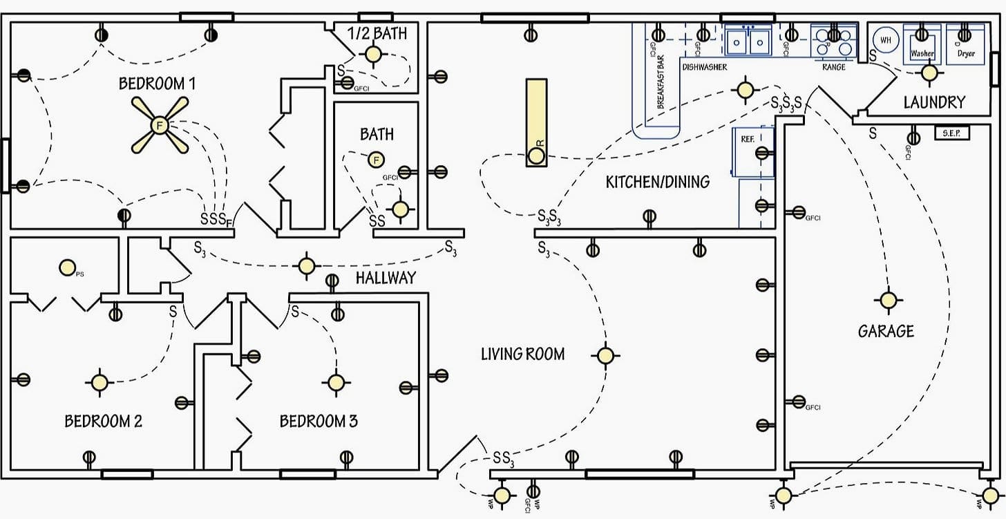
Dashed lines are drawn between the symbols to denote which switches control specific lights or receptacles.
There are quite a few symbols used to represent the devices used in home electrical wiring but some of them are very similar, so care should be used when working with them!
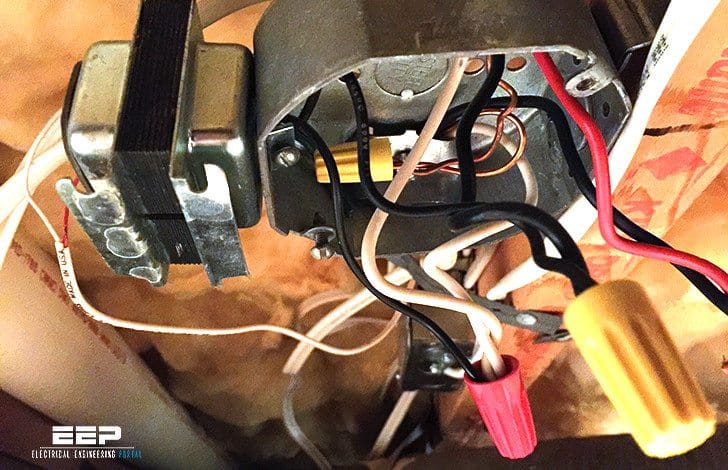
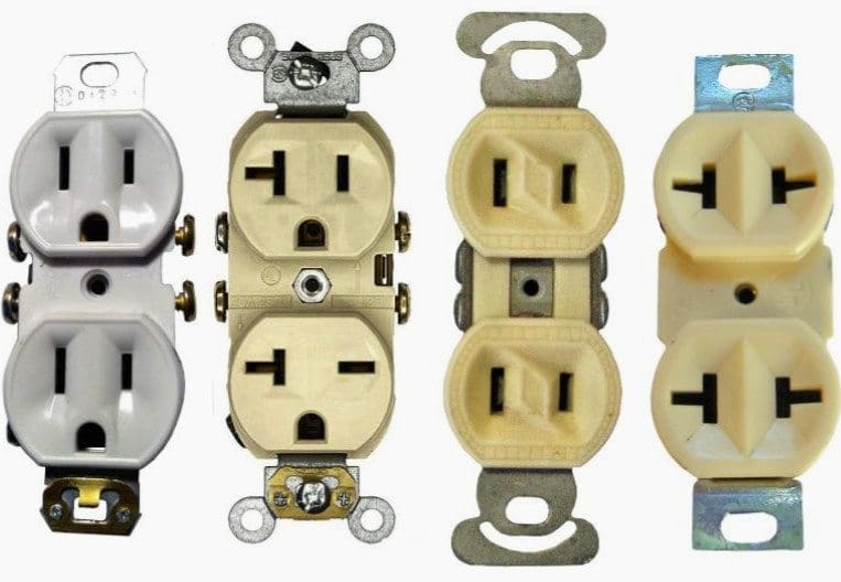
An “outlet” is any point in an electrical system where current is taken out of the system in order to supply power to the attached electrical equipment. An outlet can be one of two basic types: A “Receptacle” outlet or a “Lighting” outlet.
A receptacle outlet is one in which one or more receptacles are installed for the purpose of attaching “plug and cord-connected” type devices, and a lighting outlet is one intended for a direct-wired connection to a lamp holder, luminaire (lighting fixture) or ceiling fan.
How electricity travels throughout the home?
Electricity is supplied to your home through your electric utility’s overhead or buried power lines. Before entering your home, electricity passes through a watt-hour meter which measures the amount of electricity used.
It then continues into your house through the Service Entrance Panel (also called a “load center”), where circuit protection devices such as circuit-breakers or fuses are located.
Electricity is then distributed throughout your home using branch circuits to provide power to appliances and lights through receptacles, switches, and fixtures.
| Title: | Basic guidelines to electrical wiring around your home – Perdue University |
| Format: | |
| Size: | 2.9 MB |
| Pages: | 38 |
| Download: | Right here | Video Courses | Membership | Download Updates |

Thanks great, but can we see a version that suits modern centrally wired installations?
So that electricians and designs can discover just how much easier it is?
NO links between light fitting and switches, just a connection to show “groups”
All “light Switches” linked on the same data bus cable (no rules as to where or how they connect.
This all means that the “control point” for each light can be changed at will, as the building use evolves.
Please contact me directly for examples and a conversation.
This site maybe very useful
the guide says that thses info should be built on previous info, where can I find the previous 4 units of 4-H?
The portal is excellent, and will remain so
Ok that’s fine and I am delighed because I am teaching electricity will use the material
I’m interested to join
Yup, just like what you said, it’s pretty obvious that using schematic diagrams is a much easier way to truly comprehend the overall layout of electrical system within our residence and how we could manage faults or damages (if any). The lightbulb in my bathroom keeps on blinking even after being switched on for a long period of time. I’ll ask my husband to get in touch with an electrician to check on the matter and make some adjustments afterwards.
My choice is my future
This page is excellent and gives out the best of technical details
quite keen on knowing installation, from tools kit, wiring material and how to wire
EEP has been amazing.
It’s very nice,. Sir i still need to know more about transforma dividing
This information is very useful and I commend those working towards the progress of the portal and giving us vital information. Pls I want to request how can this PDF be downloaded
I need information on Planning, Design and Installation of Electrical house wiring. I need to know more about the Codes governing House wiring, Cable sizing, Breaker sizing etc.
Thanks.
Mike
I am home project control engineer in the republic of northern cyprus. i want the program new please can you send it to me e mail address
The notes is so helpful.thanks for sharing it
Thanks
where can i get an intermedial switches
Thank You for sharing documents…
GREAT THANKS
Why is 12v DC not use as control voltage in substations? Especially mv Substations.
24V and 48V DC are standard voltage levels for protection relay supply and control relays.
Mostly 110 volt Dc supply used. 24 volt & 48 volt also used. Main purpose is to reduced the current level & reduced the cable size too in protection circuit.
Can some one explain how 3rd harmonics are mitigated in Delta wound tertiary winding?
i appreciated the basic teaching you have just impacted in me please connect me to you so i can learn more and be working for you
Dear Sirs,
I am power engineer and spend whole my tenure in the field of electrical energy. I have many such kind of articles whic can enhance one’s knowledge. If you permit me I will be useful to you.
Thanks,
Vikram desai
Great can you send the articals
Sir, please share the useful articles you have so that many electrical passionate people can be benefited from them.
Thank you
excellent job well done for sharing these very usefull infos thanks wish you succes
it is useful and thanks to all
iam searching about smart grid