Introduction to filter networks
A filter is a network designed to pass signals having frequencies within certain bands (called pass-bands) with little attenuation, but greatly attenuates signals within other bands (called attenuation bands or stop-bands).

An attenuator network pad is composed of resistances only, the attenuation resulting being constant and independent of frequency. However, a filter is frequency sensitive and is thus composed of reactive elements.
Since certain frequencies are to be passed with minimal loss, ideally the inductors and capacitors need to be pure components since the presence of resistance results in some attenuation at all frequencies.
Between the passband of a filter, where ideally the attenuation is zero, and the attenuation band, where ideally the attenuation is infinite, is the cut-off frequency, this being the frequency at which the attenuation changes from zero to some finite value.
The filters considered in this guide are symmetrical unbalanced T and π sections, the reactances used being considered ideal. Filters are used for a variety of purposes in nearly every type of electronic communications and control equipment.
The bandwidths of filters used in communications systems vary from a fraction of a hertz to many megahertz, depending on the application.
Basic types of filter sections
1. Low-pass filters
Figure 1 shows simple unbalanced T and π section filters using series inductors and shunt capacitors. If either section is connected into a network and a continuously increasing frequency is applied, each would have a frequency-attenuation characteristic as shown in Figure 2(a).
This is an ideal characteristic and assumes pure reactive elements. All frequencies are seen to be passed from zero up to a certain value without attenuation, this value is shown as fc, the cut-off frequency; all values of frequency above fc are attenuated.
Figure 1 – Low-pass filters

It is for this reason that the networks shown in Figures 1(a) and (b) are known as low-pass filters. The electrical circuit diagram symbol for a low-pass filter is shown in Figure 2(b).
Figure 2 – Electrical circuit diagram symbol for a low-pass filter

To summarize, a low-pass filter is one designed to pass signals at frequencies below a specified cut-off frequency. When rectifiers are used to produce the DC supplies of electronic systems, a large ripple introduces undesirable noise and may even mask the effect of the signal voltage.
Low-pass filters are added to smooth the output voltage waveform, this being one of the most common applications of filters in electrical circuits.
Filters are employed to isolate various sections of a complete system and thus to prevent undesired interactions. For example, the insertion of low-pass decoupling filters between each of several amplifier stages and a common power supply reduces interaction due to the common power supply impedance.
(b) High-pass filters
Figure 3 shows simple unbalanced T and π section filters using series capacitors and shunt inductors. If either section is connected into a network and a continuously increasing frequency is applied, each would have a frequency-attenuation characteristic as shown in Figure 4(a).
Figure 3 – High-pass filters
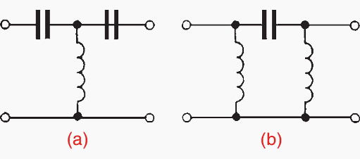
Once again this is an ideal characteristic assuming pure reactive elements. All frequencies below the cut-off frequency fc are seen to be attenuated and all frequencies above fc are passed without loss. It is for this reason that the networks shown in Figures 3(a) and (b) are known as high-pass filters.
The electrical circuit diagram symbol for a high-pass filter is shown in Figure 4(b).
Figure 4 – Electrical circuit diagram symbol for a high-pass filter
To summarize, a high-pass filter is one designed to pass signals at frequencies above a specified cut-off frequency.
The characteristics shown in Figures 2(a) and 4(a) are ideal in that they have assumed that there is no attenuation at all in the passbands and infinite attenuation in the attenuation bands. Both of these conditions are impossible to achieve in practice.
In addition to the resistive loss, there is often an added loss due to mismatching. Ideally, when a filter is inserted into a network it is matched to the impedance of that network. However the characteristic impedance of a filter, section will vary with frequency and the termination of the section may be an impedance that does not vary with frequency in the same way.
To minimize losses due to resistance and mismatching, filters are used under image impedance conditions as far as possible.
(c) Band-pass filters
A band-pass filter is one designed to pass signals with frequencies between two specified cut-off frequencies. The characteristic of an ideal band-pass filter is shown in Figure 5.
Figure 5 – Characteristic of an ideal band-pass filter
Such a filter may be formed by cascading a high-pass and a low-pass filter. fCH is the cut-off frequency of the high-pass filter and fCL is the cut-off frequency of the low-pass filter. As can be seen, fCL > fCH for a bandpass filter, the passband being given by the difference between these values.
The electrical circuit diagram symbol for a band-pass filter is shown in Figure 6.
Figure 6 – Characteristic for a band-pass filter

Crystal and ceramic devices are used extensively as band-pass filters. They are common in the intermediate frequency amplifiers of VHF radios where a precisely defined bandwidth must be maintained for good performance.
(d) Band-stop filters
A band-stop filter is one designed to pass signals with all frequencies except those between two specified cut-off frequencies. The characteristic of an ideal band-stop filter is shown in Figure 7. Such a filter may be formed by connecting a high-pass and a low-pass filter in parallel.
Figure 7 – Characteristic of an ideal band-stop filter
As can be seen, for a band-stop filter fCH > fCL, the stop-band being given by the difference between these values. The electrical circuit diagram symbol for a band-stop filter is shown in Figure 8.
Figure 8 – Electrical circuit diagram symbol for a band-stop filter

Sometimes, as in the case of interference from 50Hz power lines in an audio system, the exact frequency of a spurious noise signal is known. Usually, such interference is from an odd harmonic of 50Hz, for example, 250Hz. A sharply tuned band-stop filter, designed to attenuate the 250Hznoisesignal, issued to minimize the effect of the output.
A high-pass filter with a cut-off frequency greater than 250Hz would also remove the interference, but some of the lower frequency components of the audio signal would be lost as well.
| Title: | Filter networks for electrical engineering – by John Bird |
| Format: | |
| Size: | 1.3 MB |
| Pages: | 31 |
| Download: | Right here | Video Courses | Membership | Download Updates |