130 kV sub-transmission
(Feeding point of a 50 MVA industry)
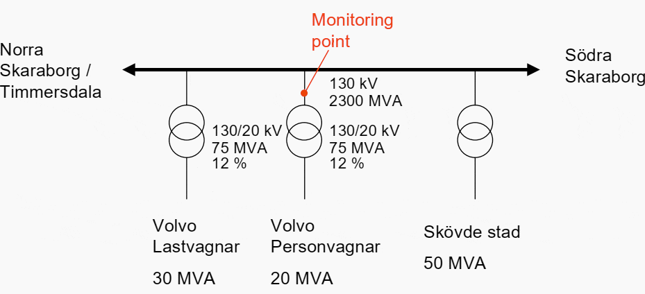
The transformer station feeds a large modern mechanical industry, divided in two parts fed by separate transformers. The phase voltage and phase current were monitored to the 20 MVA part of the industry on the 130 kV side of the 75 MVA transformer, see Figure 1. The measurements were performed in early June 1999.

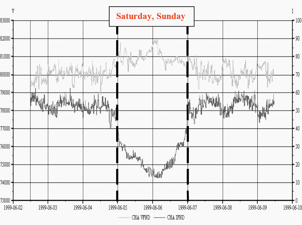
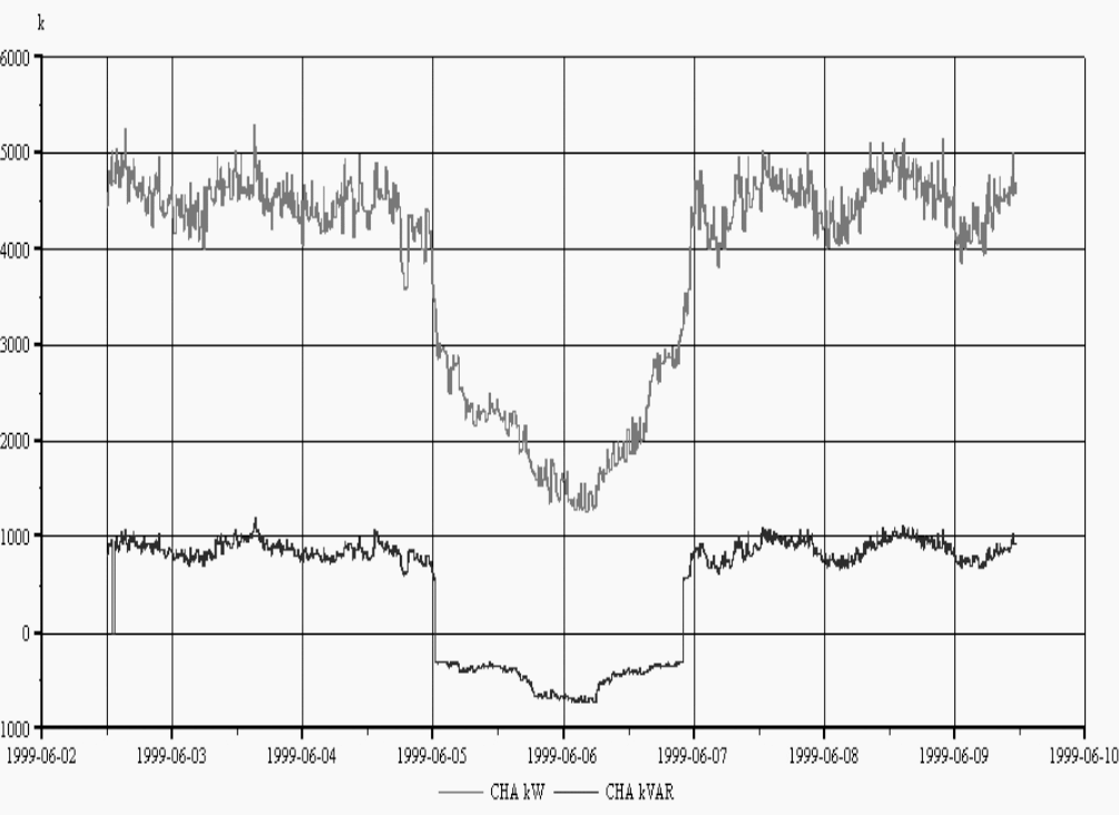
Both parts of the industry have a highly automated production and the 30 MVA part contain a number of large diode and thyristor rectifiers (a few MVA). The production was operating 24 hours a day, except Saturday and Sunday, with a small reduction over the night, Figure 2 and 3.
The current distortion (THD) at the low voltage level, on the transformer secondary side (0.4 kV), is about 25 %.

At the 130 kV level, at the 400/130 kV transformer station in Timmersdala (at 30 km distance), a 60 Mvar shunt capacitor bank is located which is connected and disconnected daily and also on demand to control the voltage on the 400 kV level.
The 30 MVA part of the industry has fixed capacitor banks. The 20 MVA part has about 5 Mvar with a mix of fixed banks and harmonic filters (harmonic 5 and 7), all at the 0.4 kV level. Of the 20 MVA load there is about 30 % induction motors, 60 % drives and other rectifiers and 10 % is office equipment and lighting.
Time variation of the fundamentals over one week
Figure 2 shows the fundamental phase voltage and current from Wednesday noon, June 2, to Wednesday noon, June 9, 1999. The large steps in the voltage are due to the switching of capacitor banks, mainly the 60 Mvar bank in Timmersdala.
The increase of the voltage during the weekend, up to 142 kV line to line voltage, is mainly due to the load reduction in the industry.

The phase current has a daily variation that follows the production, it varies between 15 and 60 A.
Figure 3 shows the fundamental active and reactive power per phase. During the weekend both the active and reactive power consumption are lower. The internal low voltage capacitor / filter banks remain connected, which cause the reactive power become negative (capacitive) during the weekend.

An important factor, from many points of view, is the fundamental voltage unbalance. For different loads, different aspects of the unbalance are important. Motors are affected by negative sequence voltage and other types of loads can be affected by the difference between the phases in amplitude or phase angle.
The negative sequence component, around 0.75 %, has a daily variation during the weekdays and the zero sequence component, around 0.65 %, shows no daily variation but a step change before, during and after the weekend.
There is no explanation for these steps in the zero sequence.
| Title: | What is harmonic distortion in a power system, and how to minimize the impacts – JOHAN LUNDQUIST, Thesis For The Degree Of Licentiate Of Engineering, Department Of Electric Power Engineering, Chalmers University Of Technology, Göteborg |
| Format: | |
| Size: | 1.2 MB |
| Pages: | 147 |
| Download: | Right here | Video Courses | Membership | Download Updates |


Hello .
I am milad from sudan . I concerned about generating free and permanent energy . so I think I had an idea for generating permanent energy . I need your help to execute it . I will share the idea if you give me a chance to discuss .
Regards