HVDC power transmission / Static var compensators
The general aspects, including application and build up, of High Voltage Direct Current (HVDC) power transmission systems and Static Var Compensators (SVC) will be described in this chapter. The HVDC and SVC techniques have very much in common since thyristors are used as switching elements in both cases.

The HvDc technique can be characterized as a technique for conversion and control of active power while the SVC technique is restricted to control of reactive power.
The HVDC technique will first be treated in this chapter followed by a section covering the SVC technique. The reason for this order is partly historical, as the HVDC technique is older, and partly depends on the fact that the SVC technique can be regarded as a compliment to the traditional at-technique as well as to the HVDC technique.
The history of HVDC goes back to the first electrical power station of 1882 as described in Ref. (1).
However, the real breakthrough came much later in 1954, when the 20 mw, 100 kV, HVDc cable transmission system between the mainland of Sweden and the island Gotland was commissioned. The convertor valve for this scheme was onercury-arc valve. Nine more HVDC convertor schemes were later built with this technique.
The last HVDC scheme using mercury arc-valves was the Nelson River Bipole T scheme in Manitoba with a rating of 1620 10 and a voltage of ± 450 kV. This scheme was commissioned in 1973.
Conmparison between HVAC and HVDC transmission system
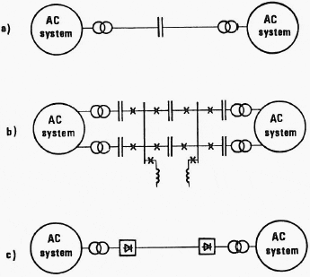
Figure 1-2 shows schematically simple transmission systems. Two electrical power systems are connected with one or two parallel HVAC-lines or a single HVDC line.

- HVAC system with a single three-phase series compensated overhead line.
- BVAC system using two parallel three-phase series compensated ovehead lines and two intermediate switching stations with shunt reactors.
- HVDC transmission with a single overhead line.
Figure 1-23 shows a case with a single HVAC-line. often such a transmission line requires installation of transformers at both ends of the transmission line to step-up the voltage at in the sending end and to step-down at the receiving end.
For most long lines with 400 kv or higher voltages the total series inductance usually has to be decreased by installation of series capacitors, as illustrated in figure 1-2a.
| Title: | High power Electronics – HVDC and SVC by The Royal Institute of Technology |
| Format: | |
| Size: | 131.6 MB |
| Pages: | 599 |
| Download: | Right here | Video Courses | Membership | Download Updates |


Something wrong with link, downloading stopped at 80%
Hello all,
The link to download this book is broken. Could you please post the fixed link?
Regards
Should be fixed now.
Can you fix link ? Downloadin stopped in 80%