Induction 1-phase watthour meter
Induction type meters are, by far, the most common form of a.c. meters met with in every day domestic and industrial installations. These meters measure electric energy in kilo-watthours. The principle of these meters is practically the same as that of the induction wattmeters.

Constructionally, the two are similar that the control spring and the pointer of the watt-meter are replaced, in the case of watthour meter, by a brake magnet and by a spindle of the meter.
The brake magnet induces eddy currents in the disc which revolves continuously instead of rotating through only a fraction of a revolution as in the case of wattmeters.
How it works?
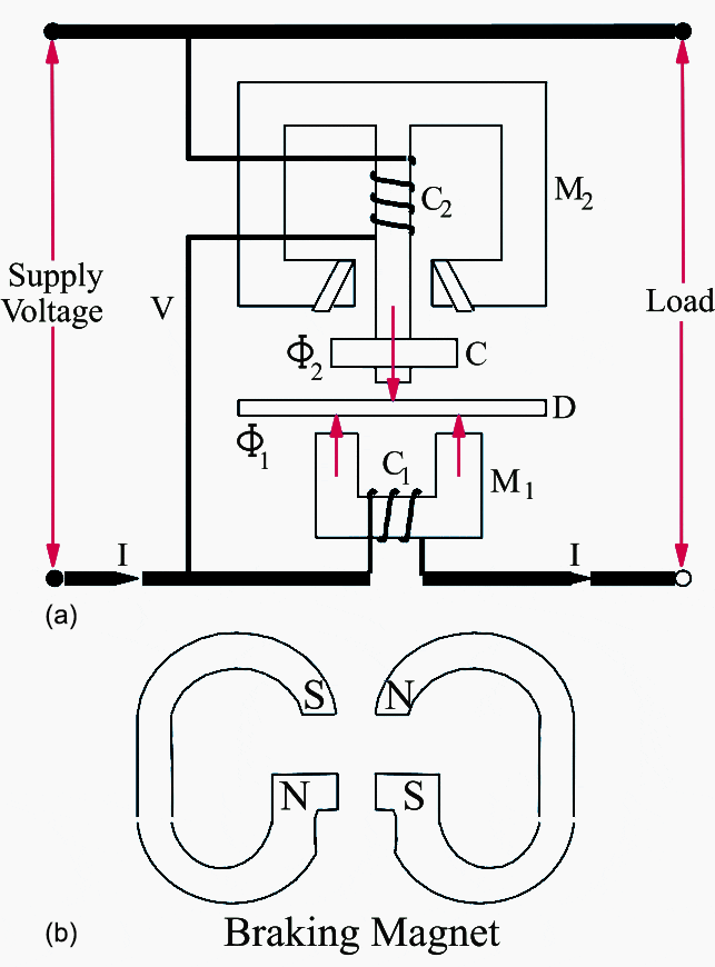
The meter consists of two a.c. electromagnets as shown in Figure 1(a), one of which i.e., M1 is excited by the line current and is known as series magnet. The alternating flux Φ1 produced by it is proportional to and in phase with the line current (provided effects of hysteresis and iron saturation are neglected).
This phase displacement of exact 90° is achieved by adjustment of the copper shading band C (also known as power factor compensator) on the shunt magnet M2.

Major portion of Φ2 crosses the narrow gap between the centre and side limbs of M2 but a small amount, which is the useful flux, passes through the disc D.
The two fluxes Φ1 and Φ2 induce e.m.f.s in the disc which further produce the circulatory eddy currents. The reaction between these fluxes and eddy currents produces the driving torque on the disc.
This arrangement minimizes the interaction between the fluxes of M1 and M2 and between the fluxes of M1 and M2 and that of the braking magnet.
When the peripheral portion of the rotating disc passes through the air-gap of the braking magnet, the eddy currents are induced in it which give rise to the necessary torque. The braking torque TB ∝ Φ2 N/R where Φ is the flux of braking magnet, N the speed of the rotating disc and R the resistance of the eddy current path.
If Φ and R are constant, then TB ∝ N.

The register mechanism is either of pointer type of cyclometer type. In the former type, the pinion on the rotor shaft drives, with the help of a suitable train of reduction gears, a series of five or six pointers rotating on dials marked with ten equal divisions.
The gearing between different pointers is such that each pointer advances by 1/10th of a revolution for a complete revolution of the adjacent pointer on the main rotor disc in the train of gearing as shown in Figure 2.
| Title: | The essentials of electrical instruments and measurements |
| Format: | |
| Size: | 2.80 MB |
| Pages: | 45 |
| Download: | Right here | Video Courses | Membership | Download Updates |


I am extremely impressed with your presentation of the sound points in this article. Thank you for writing this engaging content. third party inspection companies in UAE
very knowlegeble & practically helpful