AC resistor circuits
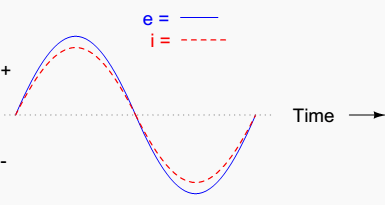
If we were to plot the current and voltage for a very simple AC circuit consisting of a source and a resistor (Figure 1), it would look something like this: (Figure 2).

Because the resistor simply and directly resists the flow of electrons at all periods of time, the waveform for the voltage drop across the resistor is exactly in phase with the waveform for the current through it.

We can look at any point in time along the horizontal axis of the plot and compare those values of current and voltage with each other (any “snapshot” look at the values of a wave are referred to as instantaneous values, meaning the values at that instant in time).

When the instantaneous value for current is zero, the instantaneous voltage across the resistor is also zero. Likewise, at the moment in time where the current through the resistor is at its positive peak, the voltage across the resistor is also at its positive peak, and so on.
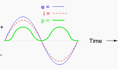
We can also calculate the power dissipated by this resistor, and plot those values on the same graph: (Figure 3).

Note that the power is never a negative value. When the current is positive (above the line), the voltage is also positive, resulting in a power (p=ie) of a positive value.
Conversely, when the current is negative (below the line), the voltage is also negative, which results in a positive value for power (a negative number multiplied by a negative number equals a positive number). This consistent “polarity” of power tells us that the resistor is always dissipating power, taking it from the source and releasing it in the form of heat energy.
Whether the current is positive or negative, a resistor still dissipates energy.
| Title: | Lessons In AC Electrical Circuits – Tony R. Kuphaldt |
| Format: | |
| Size: | 4.40 MB |
| Pages: | 570 |
| Download: | Right here | Video Courses | Membership | Download Updates |


I’m first year student of electrical engineering technology, so I’m happy to find the lessons in this digital channel
Dear friends I like to know exactly how to calculate the voltage drop and the cable size of a circuit. Please can you explain it in details. Thank for your help and good bless
Bilal Fanous
Cable resistance is calculated with R=p x L / S , where p is the conductivity of the material, L is the total length of the cable wires and S is the cross-section of the cable wires.
After calculating the cable resistance, voltage drop is simply calculated with V=R x I where I is the nominal current which flows through the cable.
If you need to reduce voltage drop, decrease the cable resistance either by decreasing the length of the cable or increasing the cross-section.