Node voltage method
The node voltage method of analysis solves for unknown voltages at circuit nodes in terms of a system of Kirchhoff’s Current Law (KCL) equations. This analysis looks strange because it involves replacing voltage sources with equivalent current sources.

Also, resistor values in ohms are replaced by equivalent conductances in siemens, G = 1/R. The siemens (S) is the unit of conductance, having replaced the mho unit. In any event S = Ω−1. And S = mho (obsolete).
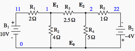
We start with a circuit having conventional voltage sources. A common node E0 is chosen as a reference point. The node voltages E1 and E2 are calculated with respect to this point.

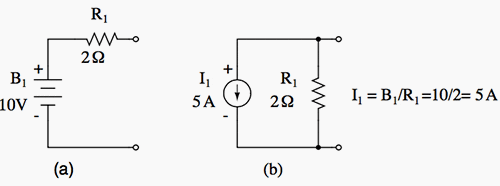
A voltage source in series with a resistance must be replaced by an equivalent current source in parallel with the resistance. We will write Kirchhoff’s Current Law (KCL) equations for each node. The right hand side of the equation is the value of the current source feeding the node.

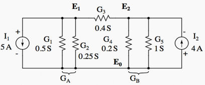
Replacing voltage sources and associated series resistors with equivalent current sources and parallel resistors yields the modified circuit. Substitute resistor conductances in siemens for resistance in ohms.
I1 = E1/R1 = 10/2 = 5 A
I2 = E2/R5 = 4/1 = 4 A
G1 = 1/R1 = 1/2 Ω = 0.5 S
G2 = 1/R2 = 1/4 Ω = 0.25 S
G3 = 1/R3 = 1/2.5 Ω = 0.4 S
G4 = 1/R4 = 1/5 Ω = 0.2 S
G5 = 1/R5 = 1/1 Ω = 1.0 S

The Parallel conductances (resistors) may be combined by addition of the conductances. Though, we will not redraw the circuit. The circuit is now ready for application of the node voltage method.
| Title: | Lessons In DC Electrical Circuits – Tony R. Kuphaldt |
| Format: | |
| Size: | 4.32 MB |
| Pages: | 570 |
| Download: | Right here | Video Courses | Membership | Download Updates |


Very useful