
Short circuits
There are 2 types of system equipment, the type that intervenes and the type that does not intervene at the time of a fault.
Passive equipment
This category comprises all equipment which, due to its function, must have the capacity to transport both normal current and short-circuit current without damage.
For this equipment, the capacity to withstand a short-circuit without damage is defined in terms of:
- Electrodynamic withstand (expressed in peak kA), characterizing mechanical resistance to electrodynamic stress.
- Thermal withstand (expressed in rms kA for 1 to 5 seconds) characterizing maximum admitted overheating.
Active equipment
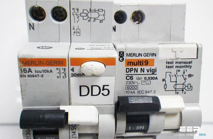
This category comprises the equipment designed to clear short circuit currents: circuit breakers and fuses. This property is expressed by the breaking capacity and if required, by the making capacity upon occurrence of a fault.

Breaking capacity
This basic characteristic of a switching device is the maximum current (in rms kA) it is capable of breaking in the specific conditions defined by the standards, it generally refers to the rms value of the AC component of the short circuit current; sometimes, for certain switchgear, the rms value of the sum of the 2 components is specified: AC and DC.
The breaking capacity requires other data such as:
- Voltage,
- R/X ratio of broken circuit,
- System natural frequency,
- Number of breaks at maximum current, for example the cycle: B – M/B – M/B (B = breaking; M = making),
- Status of the device after test.
The breaking capacity appears to be a fairly complicated characteristic to define: it therefore comes as no surprise that the same device can be assigned different breaking capacities depending on the standard by which it is defined.
Making capacity upon occurrence of a short-circuit
In general, this characteristic is implicitly defined by the breaking capacity: a device should have the capacity to “make” upon the occurrence of a short-circuit that it has the capacity to break.
Sometimes making capacity needs to be higher, for example for AC generator circuit breakers.
The making capacity is defined at peak kA since the 1st asymmetric peak is the most restrictive one from an electrodynamic point of view.
Short circuit current presumed to be “broken”. Some devices have the capacity to limit the current they are going to break. Their breaking capacity is defined as the maximum current presumed to be broken that would develop in the case of a full short circuit at the upstream terminals of the device.
| Title: | Protection and Control Guide – Merlin Gerin (Schneider Electric) |
| Format: | |
| Size: | 541KB |
| Pages: | 60 |
| Download: | Right here | Video Courses | Membership | Download Updates |

I can’t download it! ;(
Thank for your sharing.
Thanks very much for this articles. These help me a lot!