Reactive power compensator
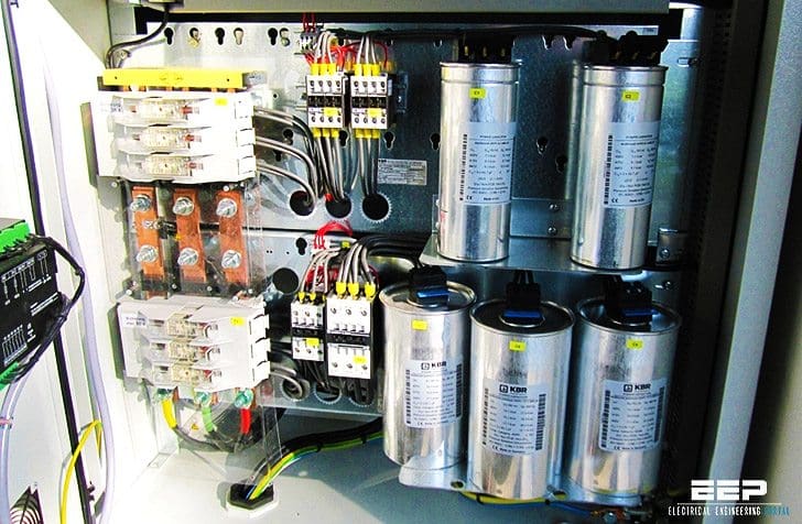
There are few solutions, that can handle the problem of reactive power compensation. One of them is reactive power compensator basing on power capacitors. This is the most popular compensating device, mainly because of economical reasons, they are relatively cheap comparing with i.e. active filters or compensation by means of electric motors.

To begin with, the aim of the project was to design automatic detuned capacitor bank for reactive power compensation with rated power of 200kVar, rated voltage of 400V and detuning factor p=7%.
One out of few assumptions was to find supplier who offers low prices and average quality as well as the one, who offers very good quality of the power factor correction equipment in order to meet the requirements of Elektrotim company customers.

The first most important thing before design process get started is to familiarize oneself with standards. Then, knowing what are the requirements regarding capacitor banks in compliance with standards I could proceed to the market survey and compare the elements capacitor bank regarding price, features and quality.
After that, when all the elements will be ordered I design main and control circuits as well as equipment layout. As a last steps, technical documentation and test program has to be done.
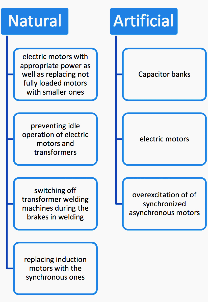
Generally speaking, a undesired power factor value caused by inductive load connected to the supplying network can be corrected (compensated) by means of loads having capacitive behaviour. Practically, there are two methods of reactive power compensation in electric networks, which are depicted on the diagram below:

| Title: | Reactive Power Compensation – Master thesis by Jakub Kępka at Faculty of Electrical Engineering |
| Format: | |
| Size: | 1.8 MB |
| Pages: | 97 |
| Download: | Right here | Video Courses | Membership | Download Updates |


Is it possible to contact the author as there are some improvements on the step selection that can be made.
He has 22kVAr being used in six steps with the finite control to a step of 20kVAr. Moving to a 1:2:4:8:8 system will improve the control. This will give a 23kVAr installation but controlled in steps from 10kVAr to 23kVAr. This is the equivalent of a 26kW load at pf 0.8 running 24/7 with no correction. The proposed amendment would reduce this to 13kW. The target pf is not stated (that I could pick up) and the economics of moving from 0.95 to 1.00 is not discussed.