Learn to to interpret drawings
After reading and studying this handbook, electricians (or would-be electricians) will have a firm grasp on the many symbols used in electrical diagrams. In particular, you will understand how to read and interpret a wide variety of electrical diagrams and plans, and how to use them together for analysis and repair.

You will become familiar with the many types of diagrams and how to distinguish between them, as well as how to choose the appropriate diagram for a given situation and how to comprehend a logic sequence and a combinatory sequence.
You will learn how to define the symbols that should be used according to the type of electrical diagram, clarify the choice of a symbol that should be used on a plan, specify why representation standards are used, and associate a type of standard with a type of symbol through the use of this handbook.
By studying the handbook, you should be able to observe the symbol system when drawing up electrical plans and diagrams. It’s important to be familiar not only with the “pure” field of electricity, but also associated, related families such as instrumentation, pneumatics, hydraulics, electronics, systems, etc.
In some specific situations, you must be prepared to train non-electricians in electrical diagram representation, and this handbook will provide you enough knowledge to do so.
But what type of diagram is required? We will look at the main types used below.
Different Types of Electric Diagrams
- Wiring and connection diagram: This shows all the connections existing between the various elements in an electric installation.
- Schematic diagram: To enable the reader to separate and keep track of each step, each level of successive (sequential) operations from the first action (initiation) to the “final act“.
- One-line diagram: Simplification of low and/or high voltage distribution, to provide an “overview” of the installation.
- Block diagram: This is a “simplified” diagram showing the steps or description of an operation if there is no need to go into detail.
- Logic diagram: This is a bit like a block diagram. Often used as a troubleshooting tool showing the various possible dysfunctions and the “initiatives” to take and the “directives” to follow according to the different possibilities, occurrences and events in the course of a sequence.
- Earthing diagram: This is a diagram which is very often forgotten after site construction. It shows all the earth/ground distribution systems with the cabling (buried or not), earthing pits, earthing connection points on equipment (by number and connection method). On site it will have an accompanying connection details book.
- Other plans/diagrams: Electricians use industrial programmable logic controllers (PLC). In the “Automatic controllers” course, we will look at the diagrams for automatic controllers themselves (ladder diagrams), but before drawing up this (final) diagram, here we will look at the systems/methods laying the groundwork for making this automatic controller diagram, i.e. logic diagram with binary logic, Boolean algebra, Boolean diagrams, Karnaugh maps, etc.
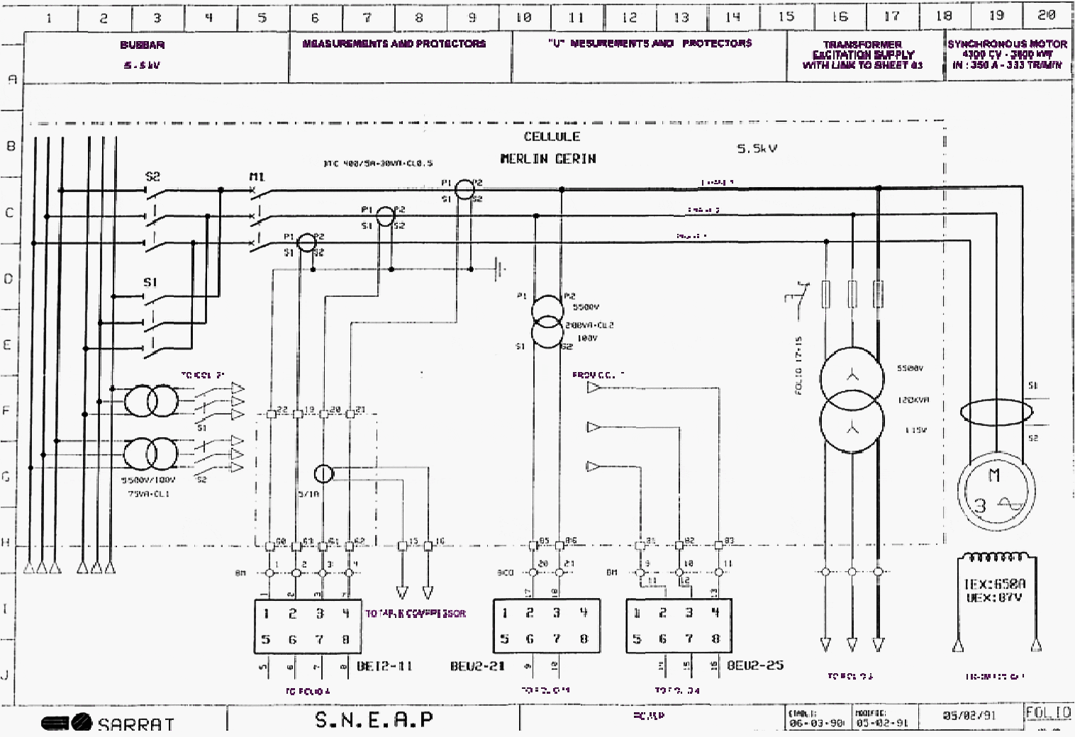
Figure 1 – Synchronous motor control: Sheet 02

Example of Diagram Reading
Now let’s go back to industrial diagrams, primarily focusing on schematic diagrams. A site electrician, for each system and distribution cabinet, has a set of plans in A3 and/or A4 format with ‘n’ sheets representing the installation “sequential” in control (or command) diagram and power diagram form.
If you are on a site, the most logical thing would be to do an application or an exercise on a ‘concrete’ example, on a real object. Get hold of the necessary sets of plans (instructors and pupils) and work on them, rather than on the example below.
But this example explains how to read and interpret a schematic diagram, and if you are a novice, you should go through the explanations and comments step by step.
| Title: | A practical handbook for reading and analysing electrical drawings and diagrams – Total |
| Format: | |
| Size: | 19.90 MB |
| Pages: | 186 |
| Download: | Here 🔗 (Get Premium Membership) | Video Courses | Download Updates |
Suggested Course – AC Panel Drawings: SLDs, Wirings, and Interlocking Schematics
Learn AC Distribution Panel Drawings: Single-Line Diagrams, Wirings, and Interlocking Schematics

