
LV Feeder Protection
We have an arrangement of a 11kV/0.415kV transformer feeding an LV (415V) switchboard. Total load is around 280kVA, with most of the three-phase motors, started DOL with few on VSD. I am proposing to use a MCCB as incomer with shut trip. It will provide thermal/magnetic protection. Do you think earth-fault and under-voltage protections are necessary for this configuration?

What is the best way of achieving earth-fault protection economically as well, e.g., CB-CT, residual CTs?
What should be the settings for both earth-fault and under-voltage relays in that case? Before you select earth-fault protection, you need to decide the system earthing for the 415V supply. Conventionally, it would be solidly grounded; but then you will have to trip when an earth fault happens and subject yourself to severe arc flash hazards.
If instead you apply high-resistance earthing, then power flow to the motors can be maintained even when there is an earth fault and there are no arc flash hazards associated with ground faults. For the size of the transformer and the load, a 2A let-through, 230V, neutral-earthing resistor would be sufficient.
This relay can be set for 1A pickup. This would be quite economical. To get more information on high-resistance grounding, you can get technical information here.
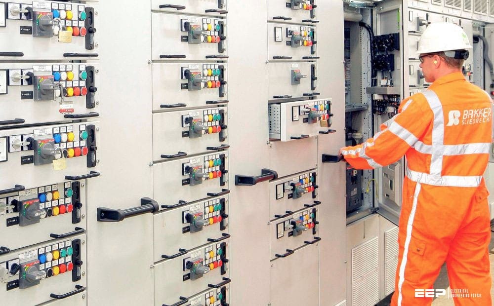
Figure 1 – Low-voltage MCC feeders
If you decide not to use high-resistance grounding and instead opt for solid grounding, then you could choose an earth-fault relay set ting of 100A. This can be obtained through an earth-fault element on the incomer MCCB, which has built-in CTs and a loose neutral sensor. Time delay setting should be as low as possible to reduce the fault damage, about 0.1 to 0.5 seconds.
There are time/current coordination issues with load-side protective devices that you will need to consider to avoid nuisance tripping the MCCB,
another problem with SG systems. The under-voltage function needs to be set for 80% of the nominal.
With a large percentage of the loads being motors under single-phasing conditions, the open phase will regenerate and would be difficult to detect if under-voltage setting is below 80%.
Zone-Selective Interlocking (ZSI)
How can zone-selective interlocking reduce the arc flash hazard from ground faults? Arc flash hazard is quantified by the incident energy released in an arc flash at a particular location, expressed in calories per centimeter squared, as determined by an arc flash hazard analysis.
The incident energy is proportional to the length of time the arcing fault persists; hence, arc flash hazard can be reduced by lowering time delay settings of the phase and ground-fault overcurrent protective devices.
The drawback of time-current coordination is that extra time delay is required on upstream protection devices. More damage is tolerated from upstream arcing faults in the interests of service continuity.
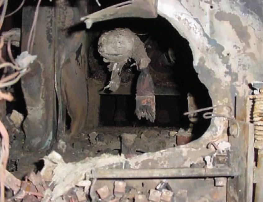
Figure 1 – Low-voltage switchgear incident due to arc-flash incident
Today, there is increased awareness of arc flash safety; engineers and electricians are taking a second look at these tripping time delays upstream in the distribution system. Arc flash safety now overrides service continuity on switchboards that require inspection while energized.
Zone-selective interlocking (ZSI), also known as zone-selective instantaneous protection (ZSIP), offers an excellent solution to this problem. It improves arc flash safety upstream in the plant distribution system without affecting service continuity.
ZSI is applied both to phase over-current devices (on the short-time protection function) and to ground-fault protective devices. It is available on electronic trip units and relays of circuit breakers. With ZSI, a breaker which senses a fault will trip with no intentional time delay unless it receives a restraint signal from the breaker immediately downstream; if so restrained, the breaker will wait to time out before tripping.
Zone-selective interlocking has been available for decades but has not been widely used because time-current coordination was deemed safe enough; damage upstream in the distribution system was a tolerable trade-off. However, the push today for increased arc flash safety means that shorter trip times will be used.
The cost of the ZSI twisted-pair control wiring between switchboards, panelboards, and motor control centers will now be considered a worthwhile investment because it improves arc flash safety without compromising service continuity.
Study more – Dos and don’ts in creating operation logic diagrams for LV and MV switchgear feeders
Dos and don’ts in creating operation logic diagrams for LV and MV switchgear feeders
Neutral Grounding Resistor Installed on Three Transformers Working in Parallel
A local utility system consists of three step-down transformers from 13.2kV to 4.16kV in parallel (delta/Y system) is solidly grounded. All transformers are feeding a common 5kV switchgear bus with two tie breakers and outgoing feeders vacuum circuit breakers. It was required to limit ground fault of the system considering limitations on cable shielding.
Present L-G fault values are within 16kA to 20kA (depending on location). One solution would be to install Neutral Ground Resistor (NGR) on existing transformers to L-G limit fault current below 1000A.
1. What are the pros and cons of that solution?
The pros would be that you limit the fault current to 1000A. By limiting the fault current, you are allowed the time to isolate only the faulted feeder and allow all non-faulted feeders to stay online. The con to this type of system is the additive line-to-ground-fault current when a tie is closed.
Instead of having 1000A, there are 2000A when two transformers are connected via a tie if you are paralleling. If you are limiting the fault current to 1000A, the resistor will have to be rated for a short-duty cycle; 10 seconds would probably be the most common.
The other con is that you have to isolate the faulted circuit. Had you chosen to limit the fault current to 5A or 10A per transformer, then it may be possible to not trip at all during a ground fault.
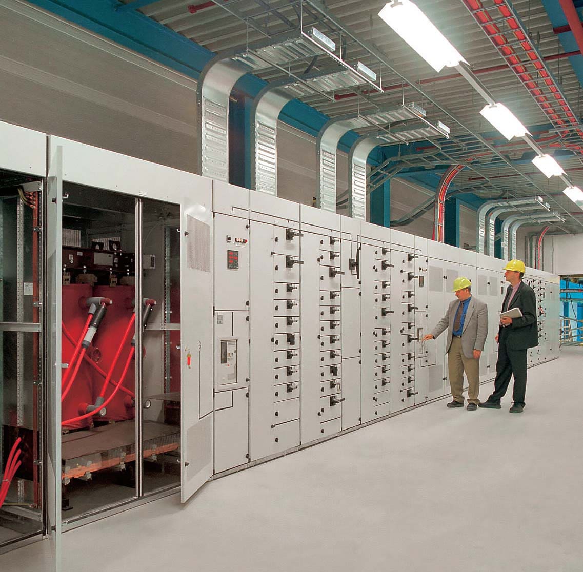
Figure 3 – Combined low-voltage switchgear with cast-resin distribution transformer
2. What type of difficulties could be faced when it comes to relay settings?
Relay settings. The difficulty with relay settings would be that you would have to consider all possibilities. Are you paralleling? Ties open? Closed? Other than that, it should be fine.
3. What would be more advisable: to install resistor on all three transformers or one common ground resistor?
The only way you can safely use one resistor is to connect all neutrals together and place one resistor on the common neutral to ground. I would never recommend this, since you can never treat the transformer as completely isolated and dead or safe because the neutral can elevate to 2400V during the presence of a ground fault without notice.
You would have to use isolation switches in order to service the transformers, and that can be costly.
| Title: | Resistance grounding booklet: Question and answers with industry experts by Gard |
| Format: | |
| Size: | 4.10 MB |
| Pages: | 40 |
| Download: | Right here | Video Courses | Membership | Download Updates |
Highly Recommended – Learn AC Distribution Panel Drawings: Single-Line Diagrams, Wirings, and Interlocking Schematics
Learn AC Distribution Panel Drawings: Single-Line Diagrams, Wirings, and Interlocking Schematics
