Neutral point earth circuits
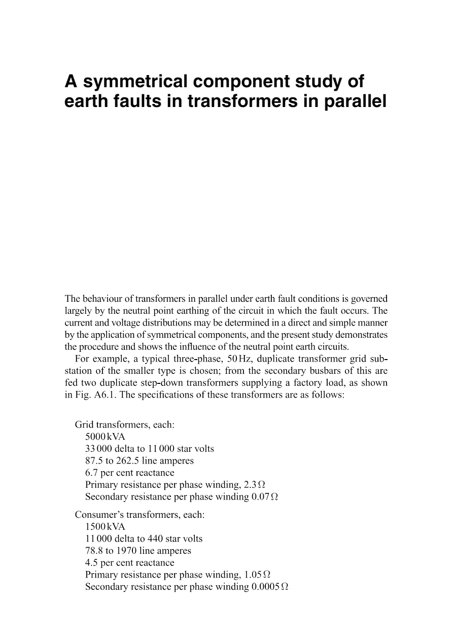
The behaviour of transformers in parallel under earth fault conditions is governed largely by the neutral point earthing of the circuit in which the fault occurs. The current and voltage distributions may be determined in a direct and simple manner by the application of symmetrical components, and the present study demonstrates the procedure and shows the influence of the neutral point earth circuits.

For example, a typical three-phase, 50 Hz, duplicate transformer grid substation of the smaller type is chosen; from the secondary busbars of this are fed two duplicate step-down transformers supplying a factory load, as shown in Figure 1.
The specifications of these transformers are as follows:
Grid transformers, each:
- 5000 kVA
- 33 000 delta to 11 000 star volts
- 87.5 to 262.5 line amperes
- 6.7 per cent reactance
- Primary resistance per phase winding, 2.3 Ω
- Secondary resistance per phase winding 0.07 Ω
Consumer’s transformers, each:
- 1500 kVA
- 11 000 delta to 440 star volts
- 78.8 to 1970 line amperes
- 4.5 per cent reactance
- Primary resistance per phase winding, 1.05 Ω
- Secondary resistance per phase winding 0.0005 Ω

The following constants will be used in the investigation:
Grid transformers:
- Primary line to neutral voltage = 19 050
- Secondary line to neutral voltage = 6350
- Secondary line to neutral reactance voltage = 6.7 per cent of 6350 = 425.5
Consumer’s transformers:
- Primary line to neutral voltage = 6350
- Secondary line to neutral voltage = 254
- Secondary line to neutral reactance voltage = 4.5 per cent of 254 = 11.42
Three cases are investigated, namely:
- Both consumer’s transformers in commission and both secondary neutrals earthed solidly.
- As (1), but the neutral of one transformer only earthed.
- One consumer’s transformer only in commission, its neutral being earthed solidly.
It is first assumed that the neutral earths of the consumer’s transformers have zero resistance, and subsequently it is shown how the fault currents and voltages are modified by earth resistance.
It is further assumed that the applied voltages at the primary terminals of the grid transformers remain balanced under fault conditions. As the fault is assumed to occur on the (LV) secondary side of the consumer’s transformers, the constants of all transformers are referred to the 440 V circuit.
This gives fault currents and voltages in terms of that circuit, and subsequently they are converted to equivalent 11 and 33 kV values in order to show the true magnitudes in all the other windings.
Resistances and reactances are expressed in ohms, and this avoids the use of an arbitrary kVA base. All constants and values are per phase, that is, line to neutral, and where delta windings are involved, their equivalent line to neutral resistances are determined first, before conversion to a different voltage base, for the sake of uniformity of treatment.
| Title: | A symmetrical component study of earth faults in transformers in parallel by Amina Mohiden at Institute of Electrical Power Systems Graz University of Technology |
| Format: | |
| Size: | 3.4 MB |
| Pages: | 50 |
| Download: | Here 🔗 (Get Premium Membership) | Video Courses | Download Updates |


I think that there would be a mechanism to provide education about transformer in schools about its benefits, its effects, and how to protect itself to avoid impact on our communities.