Vector groups & neutral earthing
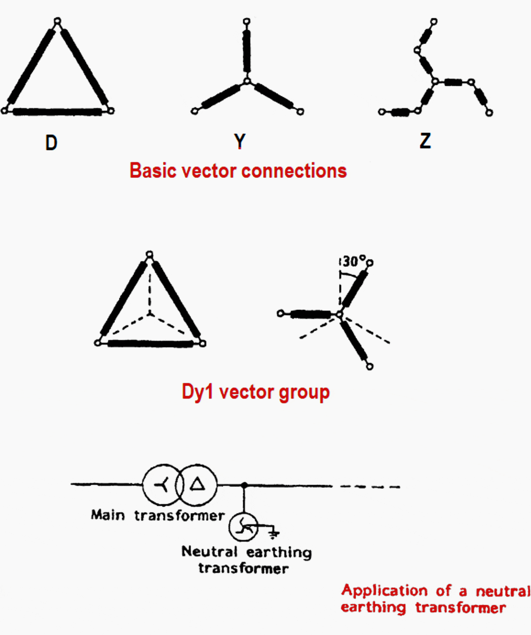
Three configurations in which three phase windings of the transformer are usually connected are delta, a star or an interconnected star (zig-zag). The configurations (winding arrangements) are shown in Figure 1 below.

How the vectors are grouped and how the phase relationship nomenclature is used are defined as follows:
- Capital letters for primary winding vector group designation
- Small letters for secondary winding group designation
- D or d represents a primary or a secondary delta winding
- Y or y represents a primary or secondary star winding
- Z or z represents a primary or secondary interconnected star winding
- N or n indicates primary or secondary winding with an earth connection to the star point
The secondary to primary voltage displacement angles are given in accordance with the position of the “hands” on a clock relative to the mid-day or twelve o’clock position.
This means: 1 is -30°, 3 is -90°, 11 is +30° and so on.

Example on defining Dy1 vector grouping is given in Figure 1 In this case, it is noticeable that the secondary star voltage is at the one o’clock position, meaning that it is lagging the primary delta voltage vector by 30°.
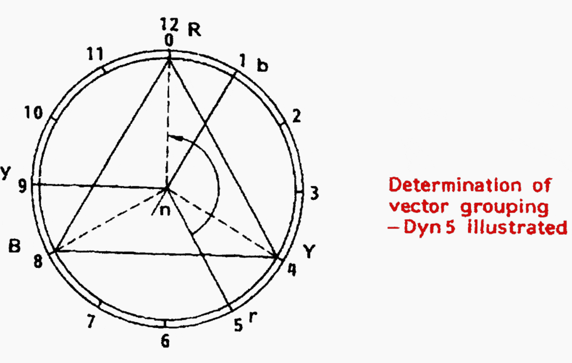
In Figure 2 below, there is another example of defining Dyn5 vector grouping.
It is clear that the secondary star voltage is at the 5 o’clock position, meaning that it is lagging the primary delta voltage vector by 5 × 30° = 150°.

Mostly the system designers are the one to decide which vector grouping arrangement is required for each voltage level in the network, though there are many factors influencing the decision.
Important aspects from user’s point of view are:
- Vector displacement between the systems connected to each winding of the transformer and ability to achieve parallel operation
- Provision of a neutral earth point or points, where the neutral is referred to earth either directly or through an impedance
- The practicality of transformer design and cost associated with insulation requirements
- The Z winding reduces voltage unbalance in systems where the load is not equally distributed between phases and permits neutral current loading with inherently low zero-sequence impedance. Therefore, it is often used for earthing transformers.
| Title: | Basic principles and operation of a transformer (Seminar paper for course Distribution and industrial networks) – Andrea Ljubljanac |
| Format: | |
| Size: | 1.0 MB |
| Pages: | 28 |
| Download: | Right here | Video Courses | Membership | Download Updates |


information are good for general knowledge.