
220/66/11 KV grid substation
The 220 KV grid substation at Sarita Vihar is a air insulated outdoor substation. This is 220/66/11 KV substation.There are four 220 KV incoming feeders for this substation coming from: Pragati Powers, Power Grid, BTPS CKT. No.1 No.2.
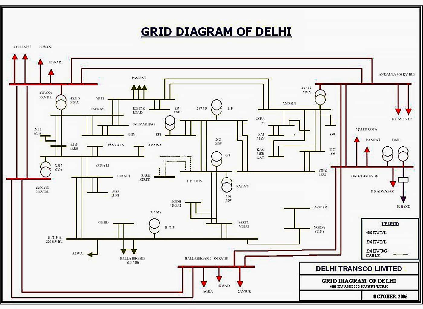
Figure attached shows key diagram of a typical 220/66/11 KV Sarita Vihar Grid Substation. The diagram of this grid station is explained as under:
-1- -There are Four 220 KV incoming lines as one circuit from Pargati powers, one circuit from Power Grid and two circuits from BTPS. These four incoming lines are connected to the double busbar system through a number of equipments.
All these lines can be loaded simultaneously to share the grid station load.
-2- As in the single line diagram the each incoming is connected to the bus bar in a sequence with a number of equipments.
The equipment between the incoming lines and the line bus bar is connected in a defined sequence as following:
- Line lightning Arrestor
- Line capacitive voltage transformer (CVT)
- Line Isolator
- Line Current Transformer
- Line Circuit Breaker
-3- The Substation has double bus bar system, one main bus bar and the other spare busbar. The incoming can be connected to either busbar with the help of an arrangement of circuit breaker and isolators called Bus Coupler.
The advantage of double busbar system is that if repair is to be carried on one busbar, the supply need not to be interrupted as the entire load can be transferred to the other bus.
-4- Each line bus bar is connected with Potential Transformer (PT) to measure the busbar voltage.
-5- There is an arrangement in to step down the incoming 220 KV supply to 66 KV by two transformer banks with capacity each of 100 MVA.
The transformer bank can be connected to either of the line bus bar through the bus changer Isolator connected between the two buses. The 100 MVA Transformer is connected to line bus bar through a number of equipments in as following defined sequence:
- Isolator arrangement
- Circuit Breaker
- Current transformer
- Isolator arrangement
- Lightning Arrestor (LA) and then
- 100 MVA transformer
-6- The 100 MVA transformer steps down the 220 KV incoming to 66 KV and this output is connected to second busbar arrangements through a sequenced equipments as follows:
- Lightning Arrestor (LA)
- Isolator arrangement
- Circuit breaker
- Busbar isolator
-7- The second bus bar arrangement is also a two bus bar system each connected with Potential Transformer (PT). There is again a bus coupler between the two bus bars to couple them.
Here a Capacitor Bank is provided to increase the incoming voltage if there is any voltage drop in the incoming. It can enhance the incoming voltage by 3 to 4 KV.
| Title: | Practical training report on 220/66/11 KV AIS substation – Md. Nafis Iqbal at National Power Training Institute (NR) Badarpur, New Delhi |
| Format: | |
| Size: | 3.50 MB |
| Pages: | 80 |
| Download: | Right here | Video Courses | Membership | Download Updates |

I am Ajay , am I try to make a report on summer training of power grid.