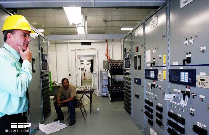
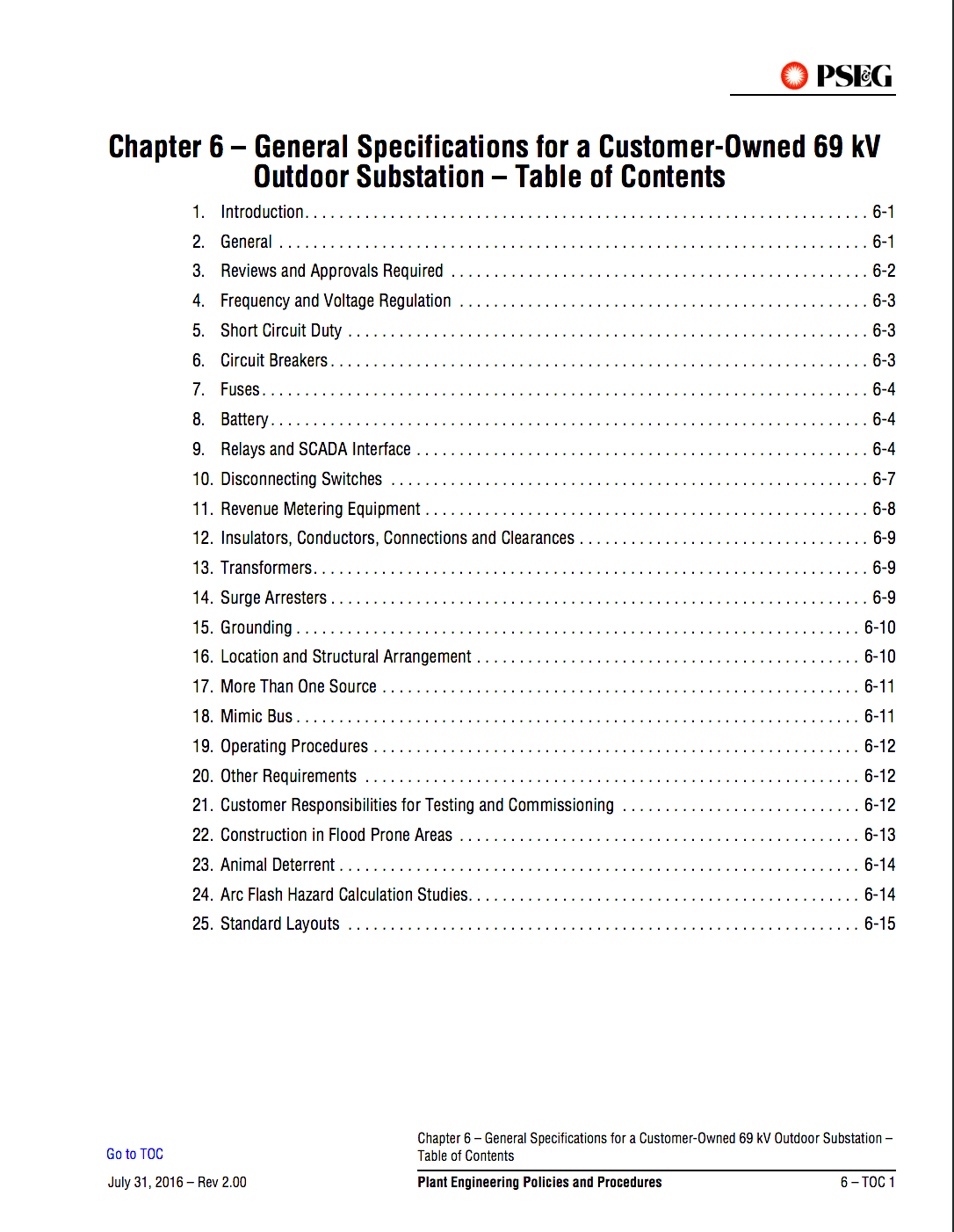
Example of 69 kV outdoor substation
Relays and SCADA interface
The following are general requirements for relaying and SCADA equipment: Specific PSE&G requirements will be provided for relays and their associated equipment, as required for the operation of circuit breakers and/or motor-operated disconnecting switches.

All proposed relay designs involving the protection of the 69 kV equipment, including single line diagram, relay and instrumentation diagrams, tripping tables, etc. must be reviewed and approved by the PSE&G System Protection Group prior to purchasing the equipment. Additionally, please contact PSE&G for approved relay types prior to the design of the protection scheme.
The customer will be responsible for applying certain relay settings provided by PSE&G using an approved third party testing company at the customer’s expense.
All protective relays shall have provisions for isolating the relays for testing or replacement purposes while the equipment is in service. Relay isolation shall be accomplished by using switches such as the ABB FT-1. Test switches in AC current circuits shall be equipped with test jacks for test connections.
The current and potential transformers supplying the relays shall not be used for any other purpose.
- All CTs for relay protection shall adhere to ANSI/IEEE Standard MRCT, C800 class or better.
- 69 kV breakers shall be equipped with two sets of three-phase CTs on both sides to provide overlapping zones of protection for incoming PSE&G lines, the customer’s 69 kV bus and 69 kV transformers, unless it is not possible to fit in two sets due to space limitations, in which case the relay and Current Transformer (CT) arrangement and accuracy class must be submitted to PSE&G for approval of the configuration.
- Each incoming 69 kV line shall be provided with three line-side single phase Potential Transformers (PTs), with a 69000/ 3-69:69 V ratio, wye-connected on both the primary and secondary sides.
It is recommended that the customer consider the installation of differential relaying for the protection of large power transformers.
If differential relaying is installed, the overcurrent relays associated with each service entrance breaker shall be connected to the bushing-type current transformers on the source side of each service entrance breaker. If CTs are not available on the source side of the entrance breaker, load side CTs may be used.
| Title: | General specifications for a customer-owned 69 kV outdoor substation by PSEG |
| Format: | |
| Size: | 732 KB |
| Pages: | 43 |
| Download: | Right here | Video Courses | Membership | Download Updates |


good article