Active distribution network
Conventionally, the electrical energy has been mainly produced by large power plants, and shipped through the transmission and distribution grids to the end customers. However, the recent quest for reduction of greenhouse gas, use of sustainable energy sources and higher energy efficiency in the transmission grid, has led to the continuous growth of comparatively much smaller Dispersed Generation Units (DGUs) exploiting renewable sources of energy and connected to Distribution Networks (DNs).

On the other hand, the existing distribution grid was not designed nor equipped to host DGUs and to become an “active distribution network”. This proliferation of DGUs raises challenges in many aspects of Distribution System Operator (DSO) activities, ranging from long-term planning to real-time control.
From system operation viewpoint, this change is expected to create new technical problems, for instance over- or under-voltages (typically in rural networks due to the long distance from the main substation), or congestion problems (typically in urban networks serving many loads).
Test systems used in this work
All distribution networks are three-phase and are assumed to operate in balanced conditions. The topology of the distribution networks is also assumed unchanged.
32-bus system
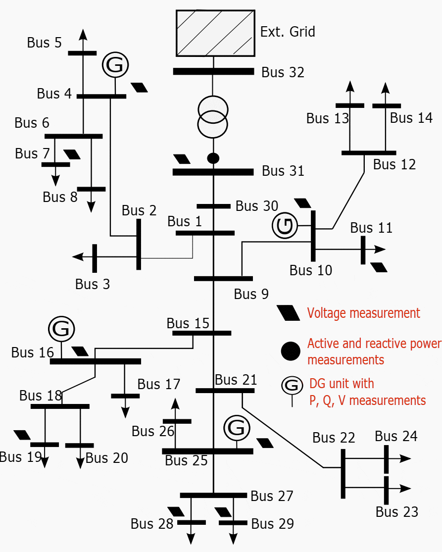
The 32-bus test system is a 20-kV distribution network connected to the external grid through a 132/20 kV transformer with fixed tap position. The network one-line diagram is shown in Figure 1 while the branch parameters are given in Table A.1.
All DGUs operate in reactive power control mode. This is achieved by a PI controller that regulates the reactive power output according to the set-point value requested by the centralized controller.
The following measurements are collected throughout the network: active and reactive power and voltage magnitude at the terminals of the four DGUs, active and reactive power flows in the HV/MV transformer as well as its terminal voltage on the MV side, and voltages at five load buses.

75-bus system
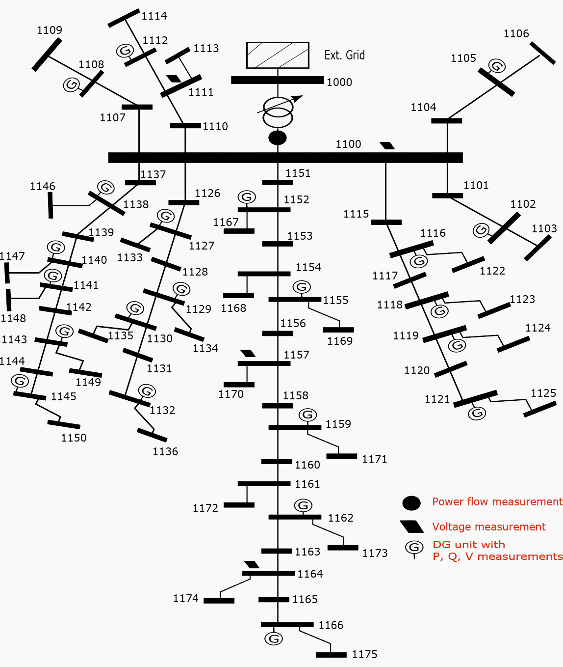
The 75-bus system is an 11-kV urban network. Its one-line diagram is presented in Figure 2, while the branch parameters are given in Table A.2. The network is connected to the external grid through a 33/11 kV transformer equipped with an LTC.
The data were taken from the United Kingdom Generic Distribution System repository which is a collection of models representative of UK distribution networks.

The system consists of eight short-distance underground feeders, all directly connected to the main transformer and serving 38 loads modelled as constant current for active power and constant impedance for reactive power, and 15 more loads represented by equivalent induction motors.
Moreover, it includes 22 DGUs which are either 3-MVA synchronous generators driven by hydro turbines with 2.55-MW nominal power, or DFIG driven by wind turbines. Each DFIG is a onemachine equivalent of two 1.5-MW wind turbines operating in parallel. The nominal capacity of each DFIG is 3.33 MVA.
As regards load buses, the measurement configuration is such that no load is at a distance larger than two buses from a voltage monitored bus, see Figure 2.
YLPIC system
The YLPIC test system is largely inspired of a Belgian MV distribution network located in Wallonia and operated by ORES. It has been used in several work packages of the GREDOR project (https://gredor.be). The objective was to examine the system behaviour over future years, when more renewable DGUs (wind and PV) would be installed.
To do so, a likely situation in 2030 has been considered with high penetration of renewable DGUs and new loads (mainly electrical vehicles and heat pumps).
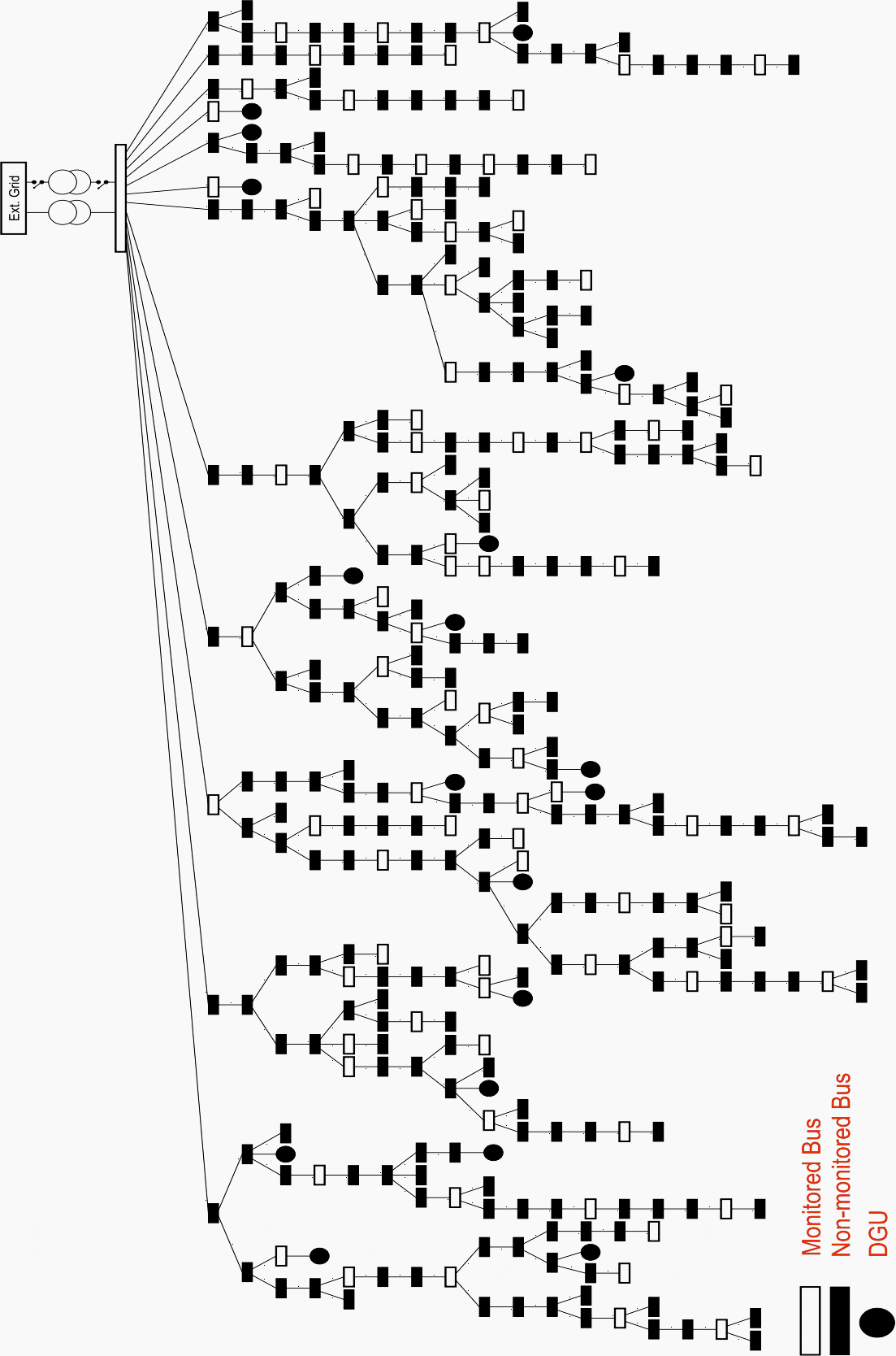
The network is a 328-bus, 10-kV distribution grid connected through two transformers to the 70-kV transmission system. The latter is represented by a Thevenin equivalent and the transformers are equipped with Load Tap Changers (LTCs). The one-line diagram is shown in Figure 3.
Main substation
The main substation hosts two 70/10 kV transformers which are connected to two separate 10-kV busbars. The latter can be connected through a bus-coupler, if needed. Each transformer has a permanent rating of 20-MVA.
Both transformers are equipped with LTCs. From past recordings it is known that the voltage on the transmission side can vary from 65-kV (0:93 pu) to 77-kV (1:10 pu), depending on the system operating conditions.
On the distribution side, however, voltages must be kept within a tighter interval.

Dispersed generation
Currently four wind-turbine units, with a total installed power of 20.5 MW, are connected to the MV buses. On the other hand, the existing PV installations as well as the Combined Heat and Power (CHP) units are all connected to the Low Voltage (LV) network.
Since setting up a communication infrastructure down to LV level does not seem realistic, DGUs connected to LV networks are not considered controllable. Instead, the focus is on DGUs connected to the MV grid.
| Title: | Real-time corrective control in active distribution networks by Hamid Soleimani Bidgoli (Submitted in partial fulfilment of the requirements for the degree of Doctor of Philosophy (Ph.D.) in Engineering Sciences at Academie universitaire Wallonie-Europe Universite de Liege) |
| Format: | |
| Size: | 11.1 MB |
| Pages: | 189 |
| Download: | Right here | Video Courses | Membership | Download Updates |


The aticle is very technical and useful for engineers desirous to become consultants specially in Power system design and analysis.
This is a very good article
need more technical online data
More information about the transformer all