Controlling capacitance in T&D network
Shunt-connected capacitors or synchronous condensers near the load centers are a common method to generate reactive power. Shunt capacitors have the advantage of providing reactive power close to the load centers, minimizing the distance between power generation and consumption, and do not have the maintenance problems associated with synchronous condensers.

Breaker switched or fixed capacitor banks, are comparatively economical and installation is also easy. Later additions according to match load characteristics are comparatively flexible.
Controlling capacitance in a transmission or distribution network could be the simplest and most economical way of maintaining system voltage, minimizing system losses and maximizing system capability
The philosophy
The application of capacitor banks and its controlling philosophy is different from location to location. For an end consumer it is used as a power factor corrector that helps to reduce his demand and avoid penalties from the energy supplier.
For a distribution company, the capacitors installed at intermediate locations on distribution line reduce line losses hence increases line capacities and improve the bus bar voltage.
For a transmission company, the intention is not only to reduce loses or increase line capacities but also to give voltage support which is an inherent system problem under heavily loaded conditions and to further delay investment costs on augmenting line and substation capacities.
Static shunt capacitors are installed near the load terminals, in factory substations, in the receiving substations, in switching substations, etc. to provide leading vars and thus to reduce the line current and total kVA loading of the substation transformer.

At generation buses, capacitor banks also can be used for voltage support though it is rare. Depending on the location and requirement, the controlling philosophy of the capacitor banks will differ. Generally, distribution capacitor banks are controlled for local requirements.
In many cases the control consists of switches that are opened and closed in a seasonal basis or some other local requirement.
But still there are grid substations which experience under voltages during some periods of the day.
Further, some of the installed capacitor banks are currently out of service due to technical problems. The main intentions of the use of capacitor banks is to give voltage support at the substation level, reduction of losses in power transformers and transmission lines, and to release the capacity constraints in transformers and lines.

Increased economic benefits can be achieved by installing more capacitor banks. Underutilizing an economical reactive power source is a factor to consider.
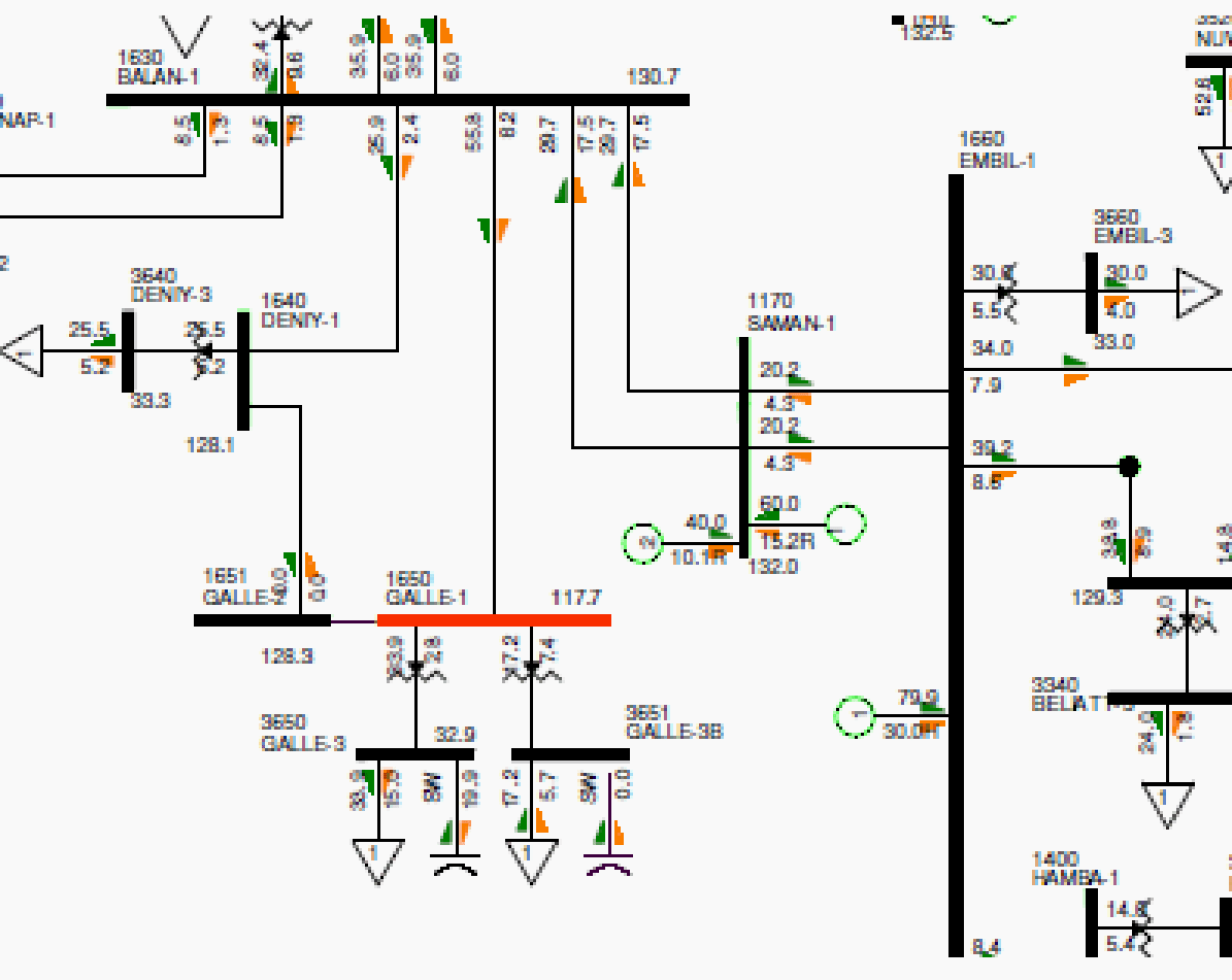
All the capacitor banks in CEB network are connected to the 33kV load bus in the relevant grid substation. This philosophy of installing the capacitor banks in grid substations does not either release the distribution feeder capacity or reduce the feeder losses. If those were expected then the capacitors could have been closer to the loads.
If the utility expects latter two cases, the switching of the capacitor banks shall be based on reactive power or voltage. In case of voltage, the banks should be switched considering the voltage measurements at the point of interconnection.
If releasing the capacity constraint or minimizing losses are concerned, then more capacitors shall be utilized to minimize drawing reactive power from remote generation.
| Title: | Adding capacitor banks to the Sri Lankan Transmission network (economic analysis) – S.A.D. Tharanga, Department of Electrical Engineering, University of Moratuwa, Sri Lanka |
| Format: | |
| Size: | 548.5 KB |
| Pages: | 39 |
| Download: | Right here | Video Courses | Membership | Download Updates |


