Substation Upgrade
Like a majority of electric utility companies, much of the utility’s transmission substation protective and control equipment is over 30–40 years old and is in dire need of upgrade and replacement.
Tiger Tie Substation
In the fall of 2002, the Utility’s engineers reviewed potential transmission substation automation upgrades for 2003 and determined that Tiger Tie substation located in Greer, SC met all selection criteria and was the best choice for performing a complete station upgrade utilizing the drop-in control house automated solution.
Tiger Tie substation is a major transmission substation in the Utility’s electric grid that delivers power to a large area of western South Carolina, including parts of Greenville, SC and Spartanburg, SC.
The Tiger Tie substation was built in the 1930s and, like most stations built at that time in the Carolinas, was built to provide voltage stability to many of the textile mills in the area. Originally, there was a small power plant built next to the station that was decommissioned in the 1960s.
The original station control house built in the 1930s was a larger brick building that housed the relay and control equipment as well as, at the time, the plant switchgear.
When additional circuits were added in the 1970s due to the lack of space in the original control house, a second metal frame building was built to accommodate future station additions. The older brick control house had various maintenance, repair, and environmental issues.
Relay panels, flooring, and ceiling contained high levels of asbestos.
Due to the obsolescence of the existing relaying and control equipment, it was apparent that a majority of the equipment needed to be replaced. Many of the cables were 45–50 years old and needed replacing.
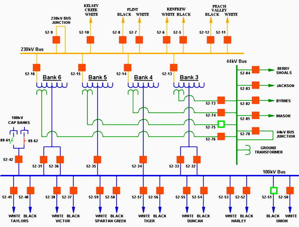
The station consists of the following equipment and circuits:
- Seven (7) 230 kV tie lines
- One (1) 230/100/44 kV 400 MVA autobank, one (1) 230/100/44 kV 200 MVA autobank, and two (2) 230/100/44 kV 150 MVA autobanks
- Twelve (12) 100 kV tie lines
- Two (2) 100 kV radial lines
- Two (2) 100 kV 80 MVAR capacitor banks
- Four (4) 44 kV lines
Existing Station Equipment
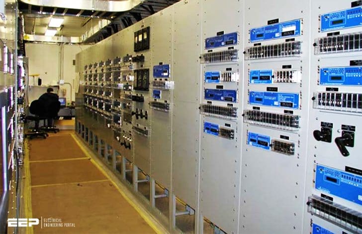
The existing protective relaying and control at Tiger Tie included a total of approximately 60 protective relaying and control panels with several thousand discrete components, including protective relays, monitoring and control devices (AFRs, RTUs, SOE recorders, PLCs), auxiliary relays, switches, and indicating lights.
Tiger Tie had two control houses, one brick building approximately 70’ x 70’ and another metal building approximately 50’ x 20’.
Tiger Tie Control House Solution
The new automated drop-in control house engineering design utilized for the relay and control upgrade at Tiger Tie provides more robust relaying, metering, and control functionality and significantly reduces the substation components.
The new design also reduced the number of unique manufactured components, electromechanical and auxiliary relays, meters, RTUs, SOEs, AFRs, and PLCs from over 100 to less than 15.
The new “drop-in” control house was significantly reduced in size to a 40’ x 16’ pre-assembled, pre-wired metal building and a separate 12’ x 12’ battery house that was set on pre- poured concrete piers.
| Title: | Experience In Implementation Of Control-Relay House For 230 kV Transmission Substation – Douglas M. Arcure (Shaw Group) and Chris Clippinger (Schweitzer Engineering Laboratories, Inc.) |
| Format: | |
| Size: | 1.9 MB |
| Pages: | 31 |
| Download: | Here 🔗 (Get Premium Membership) | Video Courses | Download Updates |