What does ‘distribution automation’ mean?
DA (Distribution Automation) means managing, protecting, using and controlling of electricity distribution networks. Automation includes different type of control and measurements functions, transferring of status of devices and alarms etc. Main automation systems in DA are a NCS (Network Control System) and a FA (Feeder Automation) system, which a DMS (Distribution Management System) supports.

The automation of medium voltage system is defined as the DA-concept. The DAconcept applies the generic word the entire distribution system operation and covers the complete range of functions from protection to SCADA (Supervisory Control and Data Acquisition) and associated information technology applications.
In this way the DA-concept integrates devices, equipment and sub systems into the one and comprehensive automation system.
Traditional model of the DA concept covers five hierarchical levels of operations: utility, network, substation, distribution and consumer layers. In these layers data and information systems used are defined:
- Layer 1 – Utility layer (IS, CIS, GIS)
- Layer 2 – Network layer (EMS, SCADA, DMS, LMS)
- Layer 3 – Substation layer (Substation control, Substation RTU)
- Layer 4 – Distribution layer (Feeder automation, DTUs, IEDs, communications)
- Layer 5 – Consumer layer (Metering and communications, LCRs, LPUs, AMR)
Where:
- IS – Information system
- RTU – Remote terminal device
- CIS – Customer information system
- DTU – Distribution terminal unit
- GIS – Geographical information system
- IED – Intelligent electronic device
- EMS – Energy management system
- LCR – Load control device
- SCADA – Supervisory control and data acquisition
- LPU – Load point unit
- DMS – Distribution management system
- AMR – Automatic meter reading
- LMS – Load management system
Distribution Automation (DA) functions
Mainly medium voltage networks are managed and controlled by DA. Main functions of the DA system are outage management, operation and control of network, remote control of substations (SCADA), SA (Substation Automation), control of network status and support functions of network management.
Outage management (clearing network failure and fault situation management) includes e.g. handling of alarms and fault reports from consumers, fault indication and calculation, remote reading of fault indicators and fault isolation.
Remote control of substations includes e.g. remote control of breakers, disconnectors and tap changers, measurements of substation busbars and feeders. Remote control systems are connected in real time to important distribution processes – development trend is integration and its expansion. Substation automation includes e.g. substation clock synchronized with overall system time and local operation like voltage control and event and alarm managements.
Network status control covers network control in normal state, maintenance and planning e.g. network map, switching situations, load estimation and prediction and remote control of network components.

Distribution Automation (DA) technologies
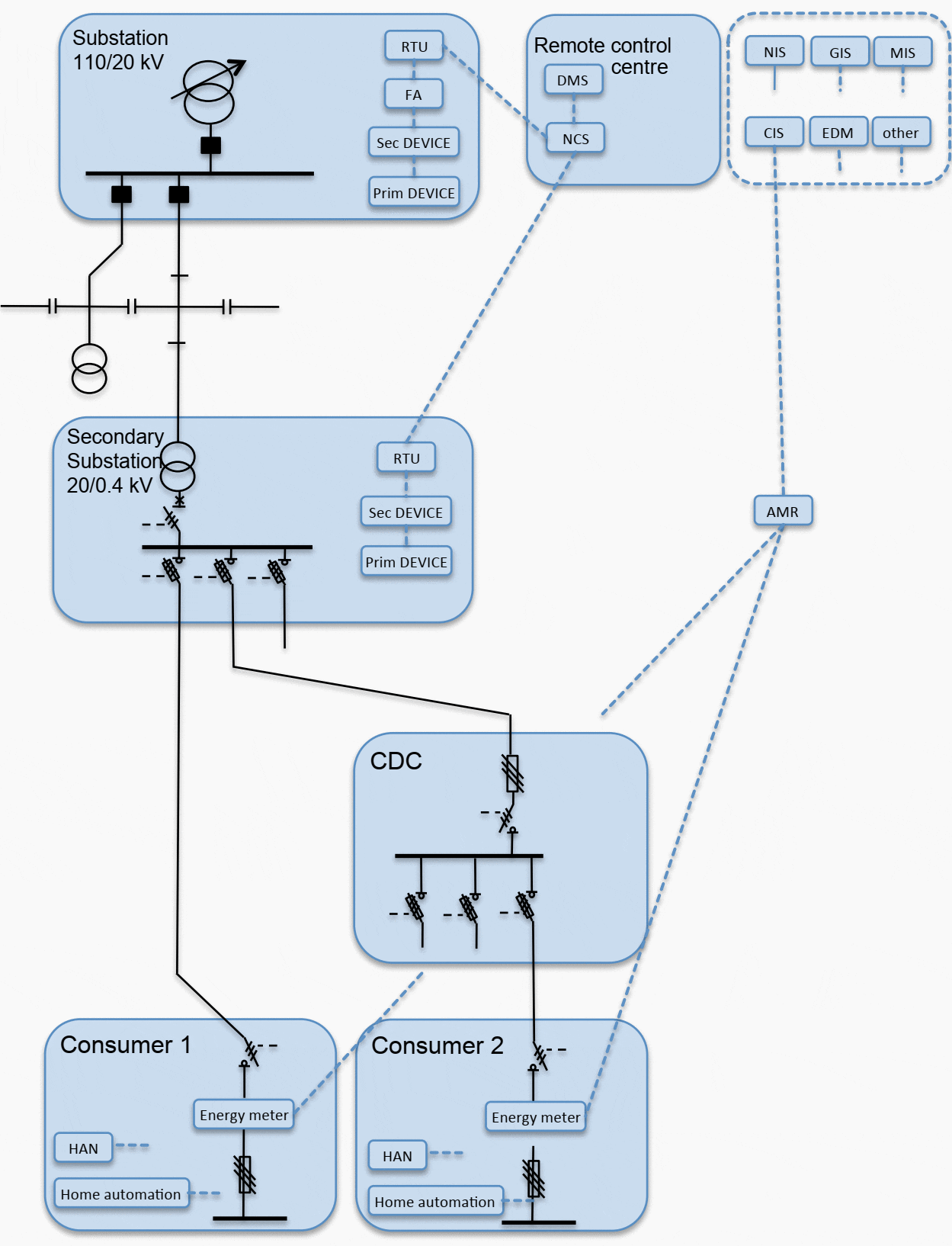
Figure 1 describes DA technologies in general, where data systems and communication are illustrated. Data systems are a DMS (Distribution Management System), which includes various applications that capitalize the information from other data systems, a NCS (Network Control System), a NIS (Network Information System), a GIS (Geographical Information Systems), a CIS (Customer Information System), a DEM (Distribution Energy Management), a MIS (Material Information System) etc.
In addition, with the help of the FA system the faults in network can be prevented. FA consists of actuators in a distribution network and terminal devices of a remote control system.

Communication in DA includes a NCS communicating with RTUs (Remote Terminal Units) in substations and with DMS in remote control centre. RTUs in substations communicate with a FA system. Secondary substation communication with the NCS arises and elaborates. CDCs (Compact Secondary Substation) are not integrated into DA. Today smart energy meters are connected at least to a CIS for billing purposes.
Home automation is still local, and connectivity to smart energy meters are considered.
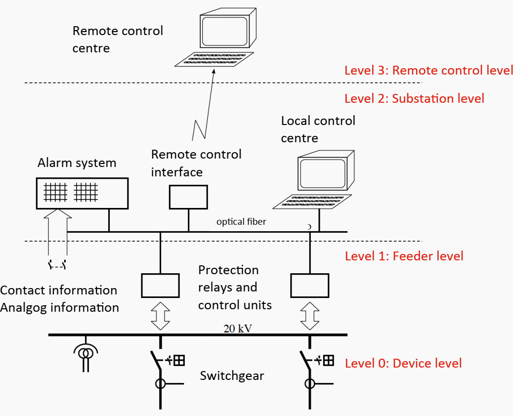
Figure 2 describes general solution of SA today. The SA system comprises secondary devices and a data acquisition system, which architecture is distributed and may be assigned to hierarchical levels, i.e. the substation level, the feeder level and the device level.
Remote control interface can be a RTU, a protocol gateway or a substation computer. Protection relays and control units are connected to communication bus, and they operate independently in network fault situations switching off the faulty part of the grid.
Today devices are at the same time communication units between local and remote control centres substituting partly functions of traditional RTU.
| Title: | Connecting LV micro grids to distribution automation – Thesis by Katja Hannele at UNIVERSITY OF VAASA, FACULTY OF TECHNOLOGY, ELECTRICAL ENGINEERING |
| Format: | |
| Size: | 4.8 MB |
| Pages: | 90 |
| Download: | Right here | Video Courses | Membership | Download Updates |


Fazermos uma grande empresa Remota via scada e Usinas
Where is project?