
Distribution systems 5kV-35kV
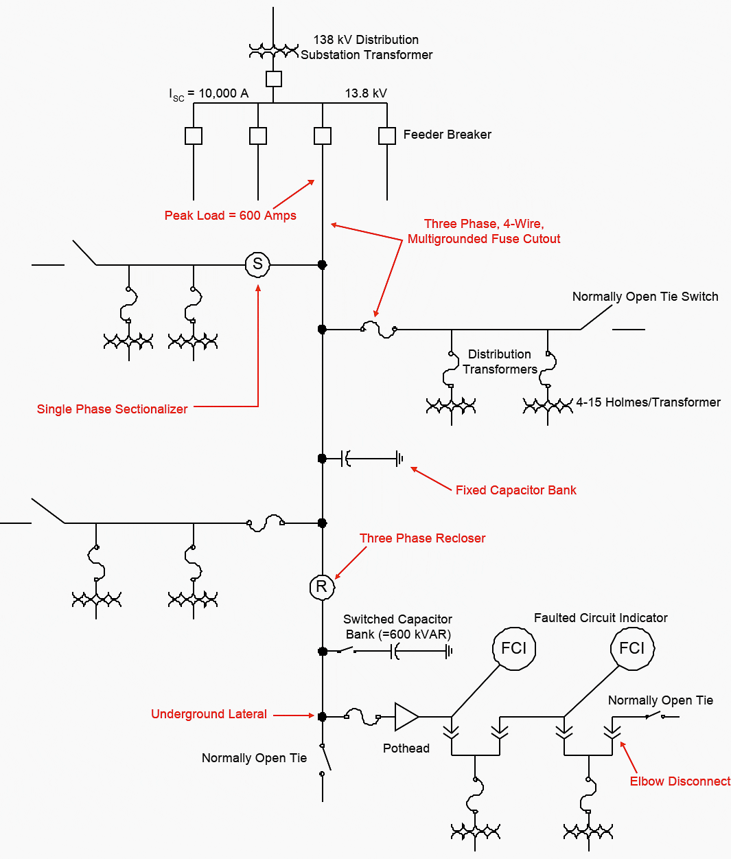
The distribution system shown below illustrates many of the features of a distribution system making it unique. The voltage level of a distribution system can be anywhere from about 5 kV to as high as 35 kV with the most common voltages in the 15 kV class. Areas served by a given voltage are proportional to the voltage itself indicating that, for the same load density, a 35 kV system can serve considerably longer lines.
Lines can be as short as a mile or two and as long as 20 or 30 miles. Typically, however, lines are generally 10 miles or less. Short circuit levels at the substation are dependent on voltage level and substation size. The average short circuit level at a distribution substation has been shown, by survey, to be about 10,000 amperes.
Feeder load current levels can be as high as 600 amperes but rarely exceed about 400 amperes with many never exceeding a couple of hundred amperes. Underground laterals are generally designed for 200 amperes of loading but rarely approach even half that value.
A typical lateral load current is probably 50 amperes or less even during cold load pickup conditions.
Fault Levels
There are two types of faults, low impedance and high impedance. A high impedance fault is considered to be a fault that has a high Z due to the contact of the conductor to the earth, i.e., Zf is high. By this definition, a bolted fault at the end of a feeder is still classified as a low impedance fault.
A summary of findings on faults and their effects is as follows:
Low Impedance Faults
Low impedance faults or bolted faults can be either very high in current magnitude (10,000 amperes or above) or fairly low, e.g., 300 amperes at the end of a long feeder.
This implies that the phase conductor either contacts the neutral wire or that the arc to the neutral conductor has a very low impedance. An EPRI study performed by the author over 10 years ago indicated that the maximum fault impedance for a detectable fault was 2 ohms or less.
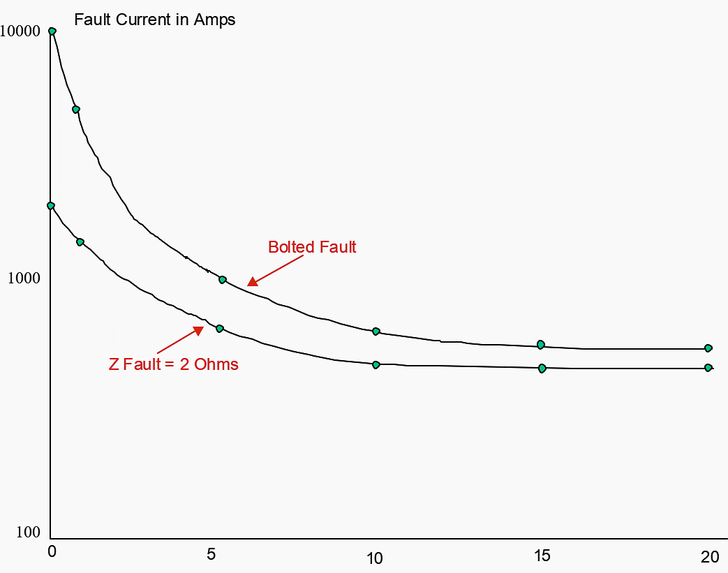
Figure 2, shown above, indicates that 2 ohms of fault impedance influences the level of fault current depending on location of the fault. As can be seen, 2 ohms of fault impedance considerably decreases the level of fault current for close in faults but has little effect for faults some distance away.
What can be concluded is that fault impedance does not significantly affect faulted circuit indicator performance since low level faults are not greatly altered.
High Impedance Faults
High impedance faults are faults that are low in value, i.e., generally less than 100 amperes due to the impedance between the phase conductor and the surface on which the conductor falls. Figure 3, shown below, illustrates that most surface areas whether wet or dry do not conduct well.
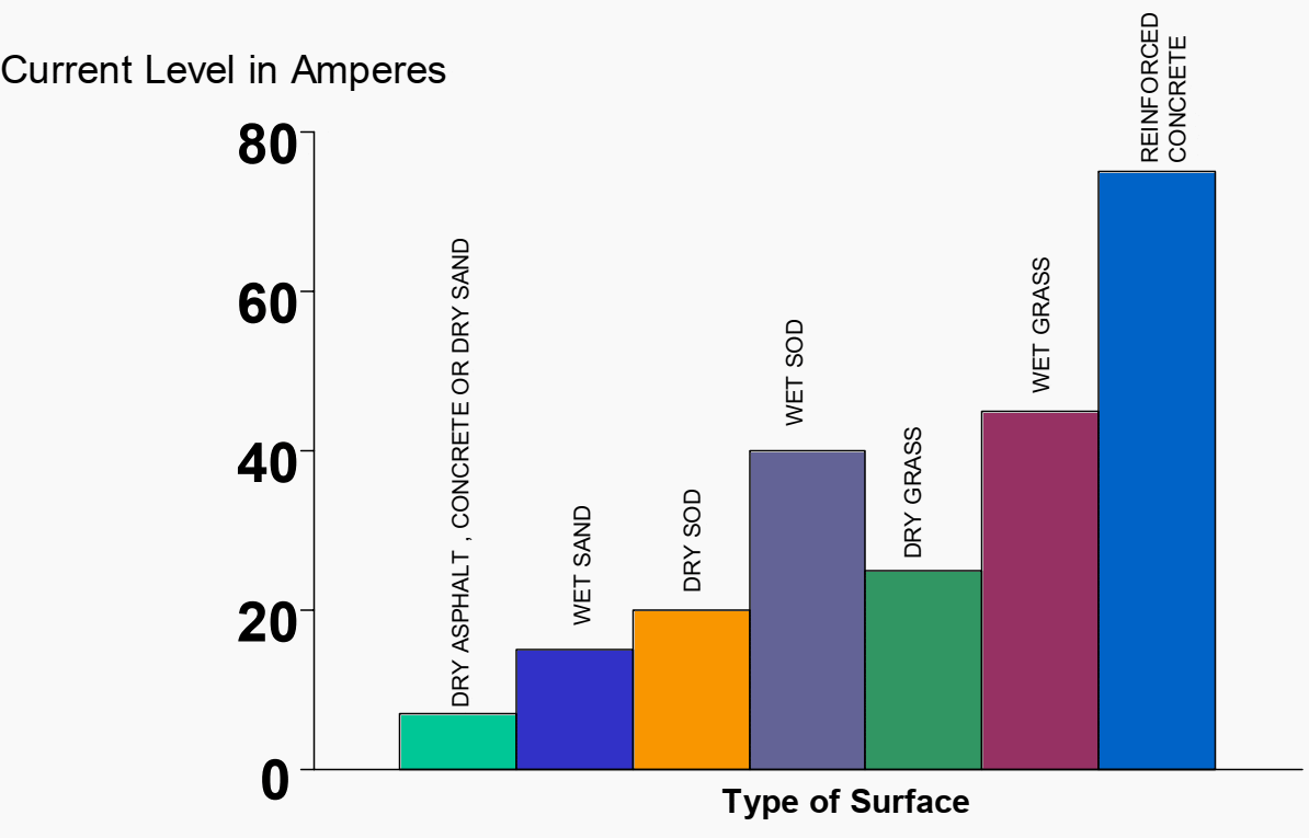
If one considers the fact that an 8 foot ground rod sunk into the earth more often than not results in an impedance of 100 ohms or greater, then it is not hard to visualize the fact that a conductor simply lying on a surface cannot be expected to have a low impedance.
These faults, called high impedance faults, do not contact the neutral and do not arc to the neutral. They are not detectable by any conventional means and are not to be considered at all in the evaluation of FCIs and most other protective devices.
| Title: | Distribution systems handbook – Jim Burke, ABB |
| Format: | |
| Size: | 0.28 MB |
| Pages: | 55 |
| Download: | Here 🔗 (Get Premium Membership) | Video Courses | Download Updates |
Suggested Reading – Dangerous threats that can compromise operation of modern digital substations and IEDs
Dangerous threats that can compromise operation of modern digital substations and IEDs

Kindly please send me electrical information