
Introduction to 100 MW AC Solar Project
The engineering drawings spanning civil, mechanical, and electrical domains provide a blueprint for constructing a robust, efficient, and highly scalable renewable energy facility. This article delves into the critical sections of the engineering drawings, highlighting the intricate details that form the backbone of this 100 MW solar plant.
The transition towards sustainable energy requires meticulous planning, precise engineering, and rigorous execution.
A prime example of this is the 100 MW AC Solar Power Plant project developed for Coal India Limited. Located in Bhadramali and Zabdiya, Gujarat, this massive infrastructure project—executed by EPC contractor Svaryu Energy Limited (formerly Refex Energy Limited)—is a masterclass in modern solar farm architecture.
Civil Engineering and Site Infrastructure
The foundation of any large-scale solar project lies in its civil engineering. The project’s civil drawings detail extensive preparatory and structural work, starting with site security. The general arrangement for the fence and gate specifies a robust perimeter utilizing chain-link fencing combined with steel barbed wire, supported by ISA 55x55x5 fence posts and corner strut posts.
The foundations for these posts mandate M25 grade concrete, ensuring long-term durability against environmental stresses. The structural steel used throughout the fencing conforms to E250 grade, coated with epoxy paint for corrosion resistance.
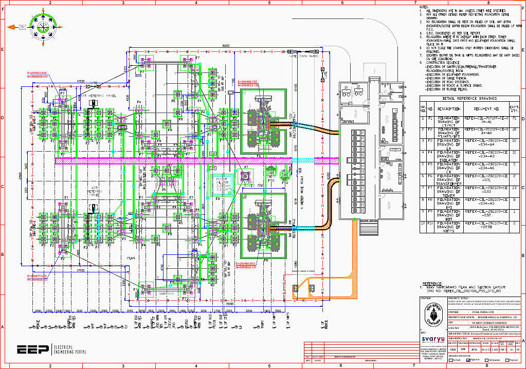
Beyond the perimeter, the civil drawings meticulously map out the structural foundations for the core power components. The drawings outline specific platforms and deep foundations for the 3.125 MW Inverter stations and the 12.5 MVA Inverter Transformers.
Switchyard tower foundations and comprehensive cable trench layouts are intricately designed to support the 66 kV pooling substation, dictating the routing of power and control cables across the facility.
The CMCS Building: The Brain of the Operations
At the heart of the solar plant is the Control, Monitoring, and Communication Station (CMCS). The architectural and foundational drawings reveal a meticulously planned Reinforced Cement Concrete (RCC) structure measuring 25 meters in length, 11.7 meters in width, and 3.4 meters in height.
The building is designed to house critical operational and personnel infrastructure.
The floor plan is segmented into specialized zones to optimize the plant’s daily operations. A spacious SCADA room, measuring 7.5 by 4 meters, serves as the central hub for real-time data monitoring and plant control. Adjacent to this are the Low Tension (LT) & UPS room (5.5 by 4 meters) and a dedicated Battery room, ensuring uninterrupted power supply to critical control systems.
Figure 1 – CMCS Building Architectural Drawing (click to zoom)
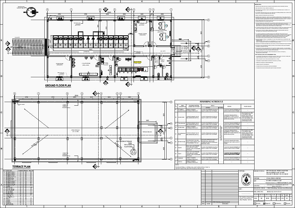
The CMCS building also incorporates an AC Supervisor room, a Pantry, a Store room, and sanitary facilities. The electrical layout within the CMCS is highly detailed, featuring surface downlighters, ceiling fans, emergency switchboards, and specific distribution boards to manage the internal power load efficiently.
The structural design mandates M-25 grade concrete with Fe-500D grade reinforcement steel, ensuring the building’s structural integrity.
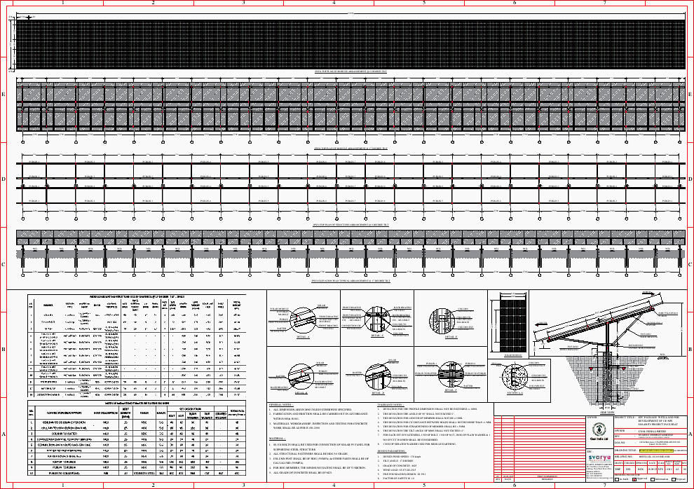
Mechanical Frameworks and Module Mounting
The mechanical section of the engineering drawings focuses predominantly on the Module Mounting Structures (MMS) and the overarching Solar PV Array Layout. The plant boasts an impressive DC capacity of 146.5 MWp to achieve the 100 MW AC output, utilizing high-efficiency 540 Wp mono-crystalline solar modules.
The arrays are designed with a portrait orientation, set at a precise 17-degree tilt angle to maximize solar irradiance capture throughout the year.
This systematic arrangement not only optimizes space but also simplifies maintenance and fault isolation.
Figure 2 – MMS foundation drawings (click to zoom)
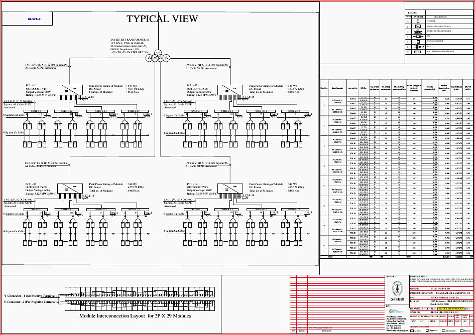
Electrical Architecture and Power Evacuation
The electrical drawings form the most critical aspect of the plant’s operational design, detailing the journey of power from the solar modules to the grid. The Single Line Diagrams (SLD) for both DC and AC systems map out the complex network of string monitoring boxes, Power Conditioning Units (PCUs), and transformers.
The plant utilizes thirty-two 3125 kVA inverters and eight 12.5 MVA Inverter Transformers to step up the voltage for efficient transmission.
The earthing design calculation and earth mat layout for the switchyard ensure absolute safety for personnel and equipment, preventing ground faults and mitigating lightning strikes.
Additionally, a fully integrated Weather Monitoring Station is included to feed critical environmental data back to the SCADA system, allowing for predictive maintenance and performance analysis.
Figure 3 – Single-line diagram (DC) (click to zoom)
Engineering Drawings Recap
The engineering drawings for the Coal India Limited 100 MW AC Solar Project reveal a deeply integrated, highly specified, and carefully calculated infrastructure plan. From the robust civil foundations and the sophisticated CMCS operations center to the optimized mechanical mounting and high-voltage electrical evacuation systems, every detail has been scrutinized.
Executed by Svaryu Energy Limited, this project stands as a testament to modern engineering capabilities, paving the way for reliable and sustainable solar energy generation in Gujarat.
| Title: | Engineering Drawings for the 100 MW Solar Project |
| Format: | |
| Size: | 31.6 MB |
| Pages: | 121 |
| Download: | Here 🔗 (Get Premium Membership) | Video Courses | Download Updates |
Further Study – 400kV Reactor Troubles Circuit Schematics: Technical Analysis
400kV Reactor Troubles Circuit Schematics: Technical Analysis
