AC and DC usability
At the end of 19th century, alternating current (AC) and direct current (DC) systems were fighting for the position of dominant electric transmission system. AC systems won the battle then, but the importance of DC electricity has increased in energy production with the rise of photovoltaic panels which output DC. DC transmission is also used today in long-distance high-voltage cables, such as transmission cables on the floors of oceans.

The integration of renewable energy production and energy storages into power grids is a common research topic. What makes this demanding is that most of PV production is installed in an LV distribution system. One option for making this easier is to change LV distribution to DC and convert the voltage to AC at the customer premises.
Microgrids are electric power systems that can operate independently from main distribution systems by having their own production units and power quality control devices.
Hybrid LV distribution system concept
The defining factor of the AC/DC hybrid distribution concept presented here is use of the neutral wire to transmit DC current along with the asymmetric component of three-phase AC current. The result is a system with one less wire compared to two separate AC and DC systems. This will naturally increase the load on the neutral wire, so DC injection to the neutral conductor must be limited when the AC system requires more of the capacity.
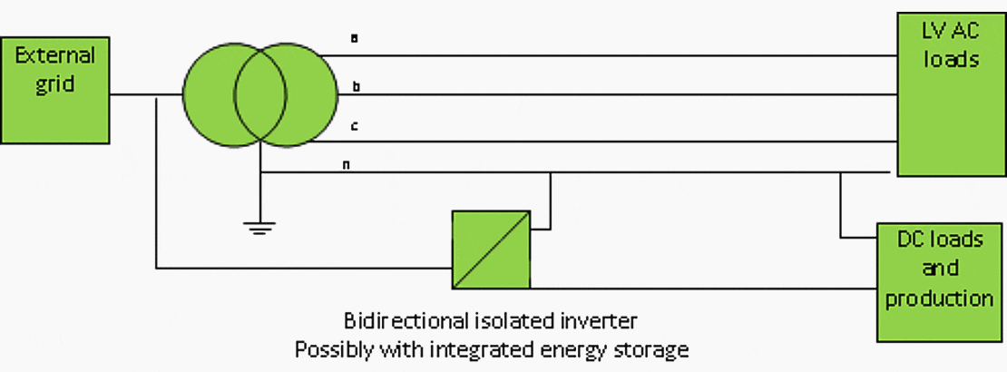
Figure 1 represents the general concept of the hybrid AC/DC distribution system.

Technical requirements and limitations
To enable use of the neutral wire for the combined DC and asymmetric component of AC current, the converter in question must have galvanic isolation on the DC side so that simultaneous operation of the DC and AC system is possible in the manner presented in Figure 1.
Without galvanic isolation, the converter would create a short circuit. Control of the converter must be capable of operation in island mode if uninterruptable power supply is needed for the AC or DC side. DC should be able to operate independently if there is a fault in the AC system and vice versa.
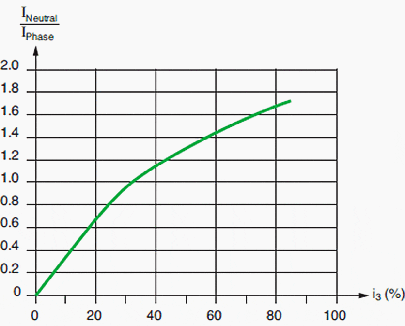
Figure 2 displays maximum current in a neutral conductor with respect to the 3rd harmonic in the phase conductor.

It can be seen from the figure that the 3rd harmonic greatly affects the neutral current, and would also take capacity from the DC current in the examined concept.
Operational modes
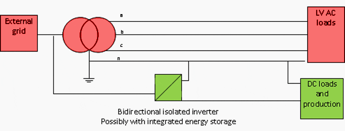
One of the main targets of the hybrid distribution concept is to achieve a system capable of operating in many different situations with respect to fault location. The following figures represent these modes. The green shapes represent parts that are functioning, and the red shapes the parts that are faulty or disconnected because of a fault.
Figure 3 displays the system in normal operation.

In normal operation mode, both systems operate in parallel. Control modes depend on how the system is to be used. On a general level, the inverter operates in power control mode, and the DC side in voltage control mode. Figure 4 displays the system with external faults.

The system should be able to continue to operate for some period after a fault occurs in the external grid. This can be described as AC/DC microgrid operation. Figure 5 displays the system with AC distribution faults.

The whole AC system could be faulted, the DC part then operating as a microgrid (assuming the fault not to be in the neutral part of the AC system). Figure 6 displays the system with DC system faults.

Similarly, faults on the DC side should not affect operation of the AC system, and the DC system should be capable of shutting down safely in a fault situation.
| Title: | The concept of hybrid AC/DC distribution system with a shared neutral – Riku Pasonen |
| Format: | |
| Size: | 1.4 MB |
| Pages: | 36 |
| Download: | Right here | Video Courses | Membership | Download Updates |


