
Development of calculation model
The practical part of thesis implies creation model of distribution network that will be able to demonstrate the effect of different non-linear loads on power quality. Also the comparison data about power losses and voltage drop in the whole network and each component of it will be obtained.
Model overview
The single-line diagram shown in Figure 1 represents designed distribution system. The electric utility distributes power at 110 kV, which in turn feeds a 20.5 kV distribution system via a 20 kV, 3-phase, 50-Hz, 10MVA distribution transformer.
Further mostly 2000 kVA service transformers are used to step the voltage down from 20.5 kV to 0.4 V. Only in one point of the distribution network a transformer with less capacity (100 kVA) is set up.
So called “basic load” is chosen to make procedure of initial data entering to system simpler. However existing model allows easily change initial load value manually.
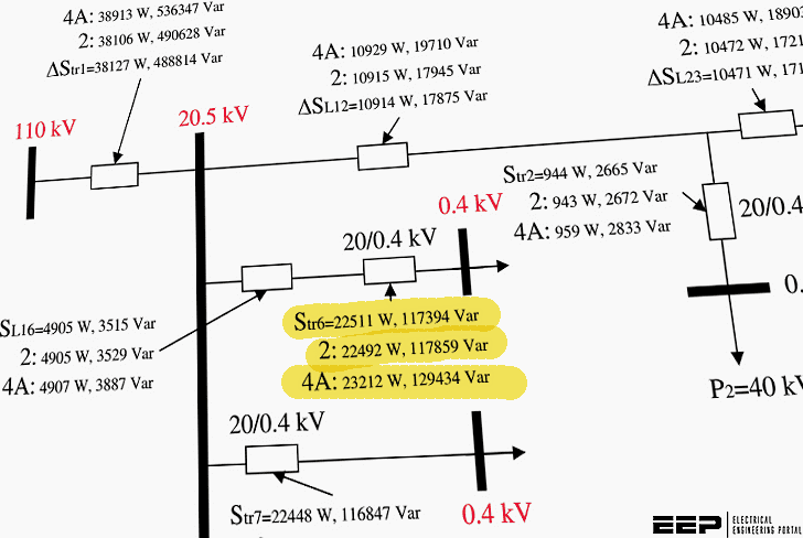
Equivalent circuit with totally linear load is given in Figure 2. Nodes are numbered for network parameters visualization. Model is designed so that it requires predefined power value of the basic load and for each harmonic.
Different approaches for evaluation of these dependences are chosen. DC resistances and inductances for lines as well as directory data for transformers are represented in Figure 2 below.
Thus obtaining all these initial data the power flow and voltage drop calculations can be done for each harmonic and eventually for summarized distorted voltages and currents. Obviously only harmonic numbers that are present in load spectrum are under consideration.
Calculation is held into two stages: power flow and voltage in network nodes calculations.
Power flow is calculated starting from customer side. By knowing the power flow inside network the further voltage in nodes is determined. This second stage calculation starts from the supplier point. In order to obtain accurate results two extra iterations are used. Voltage values in every node from previous iteration are set as the initial data.
When calculating real no-load losses in transformers for further iterations the voltage deviation is taken into account in response to following equation:
Where
- P0 – is no-load losses in a transformer,
- U2fact – is secondary voltage of a transformer,
- U2rated – is rated secondary voltage of a transformer.
Proposed calculation model requires the knowledge of network elements impedances for each frequency that is calculated.
| Title: | Effects of imbalances and non-linear loads in electricity distribution system – Nikita Lovinskiy at Lappeenranta University of Technology, Faculty of Technology, Electrical Engineering |
| Format: | |
| Size: | 1.1 MB |
| Pages: | 104 |
| Download: | Here 🔗 (Get Premium Membership) | Video Courses | Download Updates |

I would like to thank you for sharing this knowledge with me.
I will love a research in this area of power
Your articles are concise and informative for field engineers who look for information when they need theoretical analysis and field experiences.
Nice distribution transformer load discussion
Dear sir
Please sir busbar flow current and cable
Current chart pdf