Feed-in points for mobile generators
One aim of this thesis was to establish a predefined deployment plan with feed-in points on a medium voltage network for mobile generators, whereby the entire or parts of the radial network can maintain electrical security in the event of forced outages. Another aim was to make a reference chart that can be duplicated to other radial networks by using the same method of analysis as mentioned above.

During the process of working on this thesis yet another aim presented itself – testing the dpPower (distribution network management system developed by Digpro) network management system at HEMAB to see if the system could perform the same analyses with similar results.
Boundaries
I chose to analyse two radial networks, instead of one, to improve the versatility of the method used in this thesis. I am referring to these two networks as the Northern radial network and the Southern radial network. The networks I have analysed are future radial networks with underground cables.
HEMAB is aiming to replace all overhead lines by underground cables in its network by 2020. The mobile generators I have considered in the analyses are models that are currently owned and used by HEMAB, but the result in the charts are not limited to these specific models.
The analyses involve medium voltage cables between substations. Low voltage networks have not been considered, since the generators are to be connected to substations on the medium voltage side.
The analyses of power requirements are based on a worst-case scenario with full use of the substations of the radial network and not on seasonal power requirements. The reason for this boundary is that many households connected to the network in the case studies are lived in during the summer months and power consumption data is not readily available to compensate for seasonal change.
Electromagnetic Compatibility (EMC) has not been considered because of the lack of information and data about the network loads, and because EMC considerations are outside of the aim of this thesis.
Cost analyses for operation and maintenance of networks and generators have not been included and neither have power losses in the mobile transformers as they have little impact for the short duration they are in operation.
Mobile generators
In case of a forced outage HEMAB has ten mobile generators with four different power ratings that can be deployed. They are all synchronous generators driven by diesel engines. The fuel tanks can be connected to an external fuel tank for extended operation, which eliminates regular refills while the forced outage is in effect.

Calculating power requirements
To get an overall picture of the growing power requirements, starting from the tail end of the radial network and progressing upstream to the beginning, I treated each section between the substations as an island network. Each section encompassed a greater number of substations and the associated cable losses of the sections, so that each section contained a substation further upstream from the previous section.
This method allowed for line faults in every section of the radial network. With the increase in substations, the power requirements were aggregated according to the amount of substations.
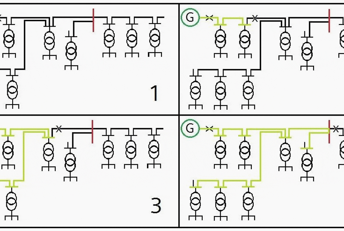
In figure 2 below, the sections, which are being fed power, are marked green. By moving the fault in the cable upstream, a new section is created and the power demand increases.

Figure 2 The figure illustrates which section of the network that has power. If the fault in the cable is moved upstream, a new section is created and the power demand increases. The figure also illustrates the networks substation transformers between both medium and low voltage busbars.
Voltage drop
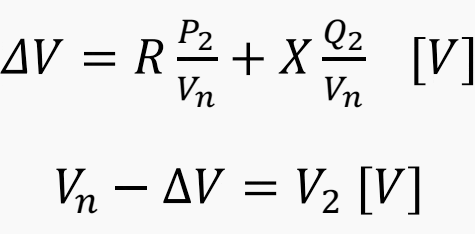
The voltage drop was calculated by using the busbar values of real (P) and reactive power (Q), with a nominal voltage of 10.4 kV, in the voltage drop equation (eq. below). The impedances have been calculated with the cable specifications and with the length of the cable.

Where:
- P = real power or in the event of several loads the sum of the real power (W)
- Q = reactive power or in the event of several loads the sum of the reactive power (var)
- Vn = Nominal voltage (V)
The voltage drop in both case studies was no greater than 46 V. According to Elkraftsystem del 2 (1997), the limit of voltage drop for a 10.4 kV line is 7 %, which equals a 728 V voltage drop. In the case studies the voltage drop is approximately 0.4 %.
After consultation with Prof. M. Bollen and HEMAB the voltage drop was considered negligible and has not been used in further calculations or considerations for voltage compensation.
| Title: | Securing radial networks in rural areas by deploying mobile generators in outage events – Adam Caffrey, Luleå University of Technology |
| Format: | |
| Size: | 1.3 MB |
| Pages: | 43 |
| Download: | Right here | Video Courses | Membership | Download Updates |
Further Study – Design of Emergency Diesel Generator Control Circuit Logic for Integration with the Utilities
Design of Emergency Diesel Generator Control Circuit Logic for Integration with the Utilities

