Capacitor banks location?
The problem described in this thesis consists on finding the best locations and sizes of capacitor banks within an electric network in order to optimize their performance. In optimization, the choice of location and sizing becomes a search for the best solution. Decision if a set of capacitor banks is better than another set is also part of the problem.
At the same time, the choice is restricted by electric network constraints. The sizes of capacitor banks are given by standard industry size, which, makes the set of solutions to be discrete. Therefore, the problem is classified as a discrete optimization problem.
The complexity of the problem arises from two aspects. The constraints of the problem, which make the solutions difficult to find if they have to satisfy many requirements. Mainly the complexity comes from the size of the network. The size of the network can make the search space grow to limits where it is not viable to screen it exhaustively.
This means that a brute-force search algorithm is in most cases impractical. Brute-force search approach is only possible in small networks.
For example, suppose there are fifty power stations in the network available to install a capacitor bank, and that into each of the power stations you can place capacitor bank of ten different sizes. Then the number of possible combinations of capacitor banks in the network is 1050.
With a bruteforce search, it will last around 1032 seconds with a supercomputer, which is much more than a lifespan. The key here is to find a optimum solution in a practical span of time.
In this project, the optimal combination of new capacitor banks is the objective. The meaning of optimum solution will be defined in Chapter 3. But now a short introduction to optimization problems will be presented. This leads to the following problem statement:
Given a electric network with known loads and power sources, find the set of new capacitor banks that installed in selected power stations, minimize the costs for a certain time period and satisfy the network constraints.
Here the key terms that defines the problem have been highlighted.
The electric network and the costs determine the form of the objective function, which has to be minimized. The set of capacitor banks and their locations are the variables that define the minimum solution. In optimization problems with constraints, there is one or more functions that we want to minimize (or maximize).
In this case, we want to minimize the function that represents the losses, the investments, operational cost of each combination of capacitor banks and cost of reactive power.
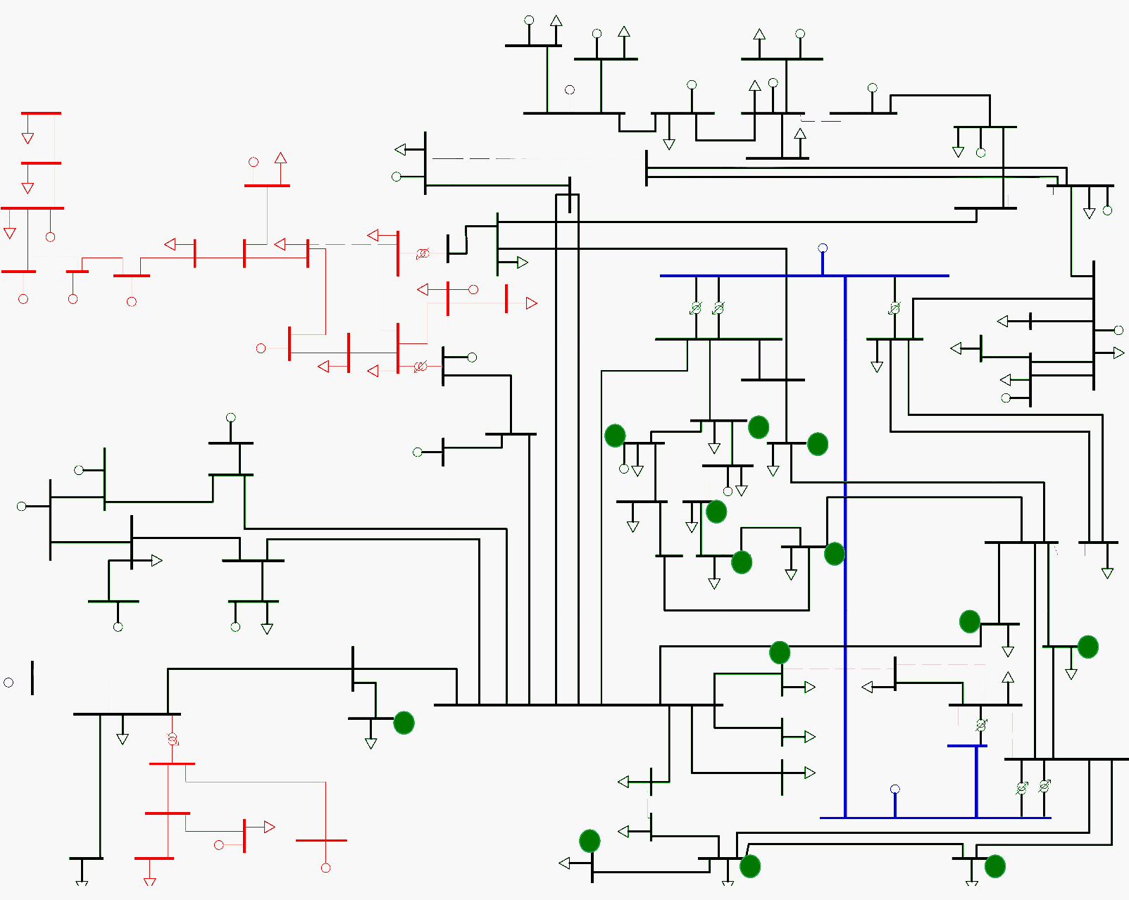
The Skagerak Network Topology
The Skagerak Nett network is composed by two networks, one in Telemark and one in Vestfold. The two networks are separated for analysis purposes, though they are interconnected in one transformer station. Both are transmission networks that have voltage levels that ranges from 56 kV to 300 kV.
However the lines of 300 kV are controlled by the Transmission System Operator (TSO). These lines are not included in the analysis as the optimization is restricted to Skagerak Nett Network. At the interconnection stations with the TSO the active and reactive power exchange is measured and traded.
The 56/66 kV power stations connect to the customers in the low voltage level through 56/11 kV or 56/22 kV transformers. The networks of 11/22 kV are distribution networks, so they are radial networks. These distribution networks will not be included in the analysis.
The analysis that will be made is just focused in the transmission network. Which is also important as there is the need, in this network, sorted by importance, to reduce losses, reduce reactive power bill and release system capacity. It is then, not a useless approach to do the analysis separating transmission and distribution networks.
Nevertheless, the reactive power losses in the distribution network can not be compensated completely by the Capacitor Bank Configuration (CBC) installed in the transmission network because the reactive power does not travel long distances.
| Title: | Optimization Of Capacitor Banks In The Skagerak Networks Transmission Grid – Héctor Marañón Ledesma, University of Agder, 2013, Faculty of Technology and Science, Department of Engineering Sciences |
| Format: | |
| Size: | 11.7 KB |
| Pages: | 127 |
| Download: | Right here | Video Courses | Membership | Download Updates |